Friday, November 22, 2013

Home theater design may require professional help

Having to be able to bring home entertainment may be a luxury. This is because only very few households can afford home theater system. Of late, only the rich and the famous can afford such luxury. This notion is now a thing of the past. Home theater systems may now be available to greater number of households because of the knowledge of basic home theater design. The basic home theater design may only require three basic components and these three components may already be affordable for the working class.


Home theater design However, before you may need to think of the basic home theater design for your home theater system, you may need to know the size of the room for the home theater set up. The size of the room to where the home theater will be set up will depend on how basic the home theater design needs to be.

Home theater experts recommends that if the room is quite small, all you need for your home theater design is a television set, three speakers and a DVD player. The home theater design may be dependent of the shpre of the room; however, the position of the speakers remains to be the left, the right and the center of the room. Basic home theater design may require a television set bigger than 27 inches. Too small screen for your home theater design may not be sufficient for a movie theater-like experience. 

This is because even for the home theater design, you may need to consider the sight and sound of a movie theater. It is the main consideration why people go to a movie theater, the big screen and the surround sound. With respect to the surround sound of a movie theater, the basic three speakers is only applicable for smaller rooms, if the room is bigger, the home theater design needs to be more than three, you may go up to six speakers and a complimenting subwoofer may be necessary for the surround effect. Going back to a small room, if you will only put three speakers, you may want to consider buying a high quality brand speaker; this will give you enough surround sound for a smaller room. 

If you have a small budget, ensure that the store where you will buy your speakers will allow you to test the product in your room and if it will not give you a good surround sound, they should allow you to return or replace the unit. This is because some speakers sound good in the store but when you finally set them up in a small room, the effect is not very good. Find a neat deal where they can allow you to return or replace the speakers. However, if your budget is sufficient, you may consider hiring the services of a home theater designer. 

Your home theater designer will be able to design the home theater better and with complete accessories. He may require checking the power rating, and the need for amplifiers. He may also recommend using home theater projectors and he may recommend how the speakers need to be. You will get a good home theater design if you will be able to hire home theater designers. The need for home theater seating and television cabinet may also be necessary for the complete package of your home theater.

You may enjoy the entertainment without having to tide traffic jam and enjoy in your own home theater system. 

[Continue Reading]

2 way Active Crossover

Therefore this architecture represents the simplest access I could booty and still get the adapted outcome.The band akin audio arresting enters the absorber area it is astern out of phase.This is to atone for the filters which will alter the appearance afresh appropriately abiding the arresting to it’s able phase. The filters are more-or-less accepted low and aerial canyon filters appropriately however, added capacitors and resistors accept been added in adjustment to get the altruism bottomward to a minimum appliance alone E12 components.


This alive Cantankerous over is adequately beeline forward. It consists of a absorber and two 3rd order, 18 dB per octave filters. One low canyon and the added high. The cantankerous over abundance is set at 2Khz and is advised for AEK’s 400watt per access PA/Keyboard Amp systems. Obviously alone one access is apparent here.

This ambit may not be of awfully abundant use to anyone as it was accurately advised to clothing the applications. It is not capricious or switchable for two reasons. Firstly, it didn’t charge to be back the backdrop of the apostle arrangement were already known. And secondly, the added complication was put into the accurateness of the crossover rather than it’s flexibility. The filters are akin in account to anniversary added as able-bodied as can be accepted appliance alone E12 components. If switching were to be active to accord a ambit of abundance options, a accommodation would accept to be fabricated on clarify accuracy.

The alone added way to accomplish a accepted crossover architecture and advance accurateness would apparently be to use Switched capacitor clarify architecture blocks. In theory, two 18or 24dB per octave filters could be complete such that they tracked anniversary added by actuality bound to the aforementioned clock. This would be a nice agreement but I haven’t had the befalling to prove this technology for this affectionate of application. My primary affair was the breach through of switching babble appliance such a design.
[Continue Reading]

Power supply with driver TEA1507

Power supply with driver TEA1507 is mostly used by TV branded PHILIPS. Power Supply has an efficiency rate of up to 90% - thus requiring less cooling, as well as stand-by power required is less than 1 watt.


Power Supply with TEA driver is equipped with a variety of surge protector that has a high reliability - not easily damaged if any part of a damaged power supply circuit and power transistor or FET heat is not easily damaged. Power supply circuits are dapatapat working on ac input voltage between 85 up to 275v. The way it works with the driver circuit power supply TEA 1507 is quite simple, so easy tracking of damage to the circuit.

Power supply with driver TEA1507

The picture above is the basic power supply circuit with TEA1507
[Continue Reading]

LM139 Measure delay generator

Measure delay generator (in addition identified in the same way as sequence generator), is a device which long for provide output signals on prescribed time intervals from a time reference to and will unconsciously reset while the input hint returns to ground. under schematic illustrates the design of a measure Delay Generator Circuit Diagram using LM139. The LM139 skin tone from head to foot precision comparators; allows sensing come close to GND; eliminates need in lieu of dual food and power drain apt for battery setup.
 Delay Generator Circuit Diagram using LM139
 Delay Generator Circuit Diagram using LM139


[Continue Reading]

Rangkaian amplifier


Technical information

Datasheet IC 5G37
Vcc                = 6-12 V
Pout               = 0,4 W
RL                 = 8 Ohm
Ft                   = 40-17 Khz
Icco               = 15 mA
Package         = TABS1-14
Manufactered = China

[Continue Reading]

Thursday, November 21, 2013

Ultrasonic Wave Receiver Circuit

Ultrasonic Wave Receiver
Ultrasonic recipients will receive an ultrasonic signal emitted by an ultrasonic transmitter in accordance with the characteristic frequency. Received signal is going through the process of filtering using the frequency band pass filter circuit, with a frequency value that is passed has been determined.


Then the output signal will be amplified and passed to the comparator circuit (comparator) with a reference voltage determined based on the amplifier output voltage when the distance between the sensor mini vehicles with bulkhead / retaining walls to reach the minimum distance for the turn direction. Comparator output can be considered under these conditions is high (logic 1 ), while longer distances are low (logica0). Binary logics are then forwarded to the circuit controller (microcontroller).


The working principle of ultrasonic wave receiver circuit are as follows:

  • First - the first received signal will be strengthened first by the circuit transistor amplifier Q2.
  • Then the signal will be filtered using a high pass filter at a frequency of> 40kHz by a series of transistor Q1.
  • After the signal is amplified and filtered, then the signal will be rectified by diode D1 and D2 series.
  • Then the signal through a filter circuit low pass filter at a frequency <40kHz through the filter circuit C4 and R4.
  • After that the signal will go through the Op-Amp comparator U3.
  • So when there is an ultrasonic signal into the circuit, then the comparator will issue a logic low (0V), which will then be processed by the microcontroller to calculate the distance.
[Continue Reading]

Bridge Power Amplifier Using TDA7294

Using TDA7294 audio amplifier integrated circuit in bridge mode configuration , can be designed another Hi-Fi power amplifier .In this TDA7294 bridge power amplifier the value of the load must not be lower than 8 Ohm for dissipation and current capability reasons.

Bridge Power Amplifier Circuit Using TDA7294


The main advantages offered by TDA7294 bridge mode configuration are:High power performances with limited supply voltage level, Considerably high output power even with high load values ( 16 Ohm).The output power of this amplifier in bridge connection is 150 W with Rl= 8 Ohm , Vs = +/-25V the and 170 W output power for Rl=16 Ohm, Vs = +/-35V.
[Continue Reading]

Hybrid Headphone Amplifier

Potentially,
headphone listening can be technically superior since room reflections
are eliminated and the intimate contact between transducer and ear
mean that only tiny amounts of power are required. The small power
requirement means that transducers can be operated at a small fraction
of their full excursion capabilities thus reducing THD and other
non-linear distortions. This design of a dedicated headphones amplifier
is potentially controversial in that it has unity voltage gain and
employs valves and transistors in the same design.

Normal
headphones have an impedance of 32R per channel. The usual standard line
output of 775 mV to which all quality equipment aspires will generate a
power of U2 / R = 0.7752 / 32 = 18 mW per channel across a headphone
of this impedance. An examination of available headphones at well known
high street emporiums revealed that the sensitivity varied from 96 dB
to 103db/mW! So, in practice the circuit will only require unity gain
to reach deafening levels. As a unity gain design is required it is
quite possible to employ a low distortion output stage.

The
obvious choice is an emitter follower. This has nearly unity gain
combined with a large amount of local feedback. Unfortunately the
output impedance of an emitter follower is dependent upon the source
impedance. With a volume control, or even with different signal sources
this will vary and could produce small but audible changes in sound
quality. To prevent this, the output stage is driven by a cathode
follower,based around an ECC82 valve (US equivalent: 12AU7).

This
device, as opposed to a transistor configuration, enables the output
stage to be driven with a constant value, low impedance. In other
words, the signal from the low impedance point is used to drive the
high impedance of the output stage, a situation which promotes low
overall THD. At the modest output powers required of the circuit, the
only sensible choice is a Class A circuit. In this case the much
vaunted single-ended output stage is employed and that comprises of T3
and constant current source T1-T2.


Hybrid Headphone Amplifier circuit schematic

The
constant current is set by the Vbe voltage of T1 applied across R5
With its value of 22R, the current is set at 27 mA. T3 is used in the
emitter follower mode with high input impedance and low output
impedance. Indeed the main problem of using a valve at low voltages is
that it’s fairly difficult to get any real current drain. In order to
prevent distortion the output stage shouldn’t be allowed to load the
valve. This is down to the choice of output device. A BC517 is used for
T3 because of its high current gain, 30,000 at 2 mA! Since we have a
low impedance output stage, the load may be capacitively coupled via
C4.

Some purists may baulk at the idea of using an electrolytic
for this job but he fact remains that distortion generated by
capacitive coupling is at least two orders of magnitude lower than
transformer coupling. The rest of the circuitry is used to condition
the various voltages used by the circuit. In order to obtain a linear
output the valve grid needs to be biased at half the supply voltage.
This is the function of the voltage divider R4 and R2. Input signals
are coupled into the circuit via C1 and R1.

R1, connected
between the voltage divider and V1’s grid defines the input impedance
of the circuit. C1 has sufficiently large a value to ensure response
down to 2 Hz. Although the circuit does a good job of rejecting line
noise on its own due to the high impedance of V1’s anode and T3’s
collector current, it needs a little help to obtain a silent background
in the absence of signal. The ‘help’ is in the form of the capacitance
multiplier circuit built around T5. Another BC517 is used here to
avoid loading of the filter comprising R7 and C5. In principle the
capacitance of C5 is multiplied by the gain of T5.

In practice
the smooth dc applied to T5’s base appears at low impedance at its
emitter. An important added advantage is that the supply voltage is
applied slowly on powering up. This is of course due to the time taken
to fully charge C5 via R7. No trace of hum or ripple can be seen here on
the ‘scope. C2 is used to ensure stability at RF. The DC supply is
also used to run the valve heater. The ECC82 has an advantage here in
that its heater can be connected for operate from 12.6 V.

To run
it T4 is used as a series pass element. Base voltage is obtained from
the emitter of T5. T4 has very low output impedance, about 160 mR and
this helps to prevent extraneous signals being picked up from the
heater wiring. Connecting the transistor base to C5 also lets the valve
heater warm up gently. A couple of volts only are lost across T4 and
although the device runs warm it doesn’t require a heat-sink.

[Continue Reading]

Wednesday, November 20, 2013

Low Current Relay

Low current relay
This low current relay circuit is designed to be used in battery operated electronic devices. Its operating current is in micro amperes (µA). This is done by using a bistable relay and adding some components to force the relay to behave like a monostable relay.


A bistable relay stays at its last state when the power is turned off but consume at least 50mA trigger current. A monostable relay switches back to its original state when the power is turned off.
Low Current Relay


How does the low current relay works?

When the power is turned ON, the C1 charges via D1 and the relay coil and this current activates the relay. D1 ensures that the base of T1 is always more positive than its emitter and because of this T1 and T2 are always blocked.

Once the power is turned OFF, the emitter of T1 is coupled to the charge voltage at the positive pole of C1. Its base and the relay coil on the other hand are coupled to the negative pole of C1 and now T1 and T2 conduct, C1 can discharge through T2 and relay. The current flows to the relay coil but in reverse order so is activated to its other state.

It has the advantage of consuming little current, around 150 µA. For a reliable operation, select the relay’s operating voltage as 2/3 to 3/4 of the main power supply. For example is using a 12V power supply select a 9V relay.

Transistors replacements:
T1 = 2SA499 = BC557, BC558
T2 = 2SC734 = BC547, BC548
Low current relay switch

source:http://electroschematics.com/6546/low-current-relay/ 
[Continue Reading]

3V to 40 Volt DC Converter Circuit

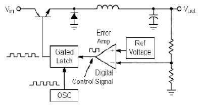
Switching regulator subsystems intended for use as dc to dc converters. 3V to 40 Volt DC Converter circuit | The use of switching regulators is becoming more pronounced over that of linear regulators because the size reductions in new equipment designs require greater conversion efficiency. Another major advantage of the switching regulator is that it has increasednapplication flexibility of output voltage. The output can be less than, greater than, or of opposite polarity to that of the input voltage.

3V to 40 Volt DC Converter Circuit

Switching regulator subsystems intended for use as dc to dc converters. 3V to 40 Volt DC Converter circuit

The MC34063 series is a monolithic control circuit containing all the active functions required for dc to dc converters. This device contains an internal temperature compensated reference, comparator, controlled duty cycle oscillator with an active peak current limit circuit, driver, and a high current output switch. This series was specifically designed to be incorporated in step–up, step–down and voltage–inverting converter applications. These functions are contained in an 8–pin dual in–line package.

FEATURES 3V to 40 Volt DC Converter :
· Wide Input Voltage Range 3 V to 40 V
· Precision Internal Reference 2%
· High Output Switch Current Up to 1.5 A
· Short-Circuit Current Limiting
· Adjustable Output Voltage
· Low Standby Current
· Oscillator Frequency Up to 100 kHz
[Continue Reading]

Automatic Emergency Lamp Circuit

This is an automatic emergency lamp with day light sensing, means it senses darkness/night and turns ON automatically. Similarly it senses day light and turns OFF automatically. A simple emergency lamp which does not require any special equipment; even a multimeter to assemble and use. Any individual who can do a good quality soldering must be able to build this circuit successfully.

This can be easily accommodated in the defunct two 6 watt tube National Emergency Lamp or any PL tube type emergency lamp. The difference will be in the working; it will work non stop for more than 8 hours. Deep discharge is taken care by the LED characteristic and over charge protection is taken care by the fixed voltage regulator.This uses a simple 3Pin fixed regulator which has a built in current limiting circuit.

Simple Emergency Light Circuit Diagram: 

Automatic Emergency Lamp Circuit
The only required adjustment is the preset which has to be set to ensure the LEDs just light up (it should be left at that position). The 5mm LDR is just mounted on top of the emergency light as shown in the photograph. LDR is used to avoid it lighting up during day time or when the room lights are ON. 2 LEDs are used in series; the dropping resistance is avoided and 2 LEDs light up with current that is required for a single LED,  by which energy is saved to a great extent.

This particular circuit has been kept so simple for people who has limited access to components or in other words this is an emergency light that you can build with minimum components. In addition to circuit diagram, He has shared photographs of the prototype he made in National emergency light and a PCB design.
[Continue Reading]

Tuesday, November 19, 2013

Simple Stabilizer Circuit Diagram

Simple Stabilizer Circuit DiagramSimple Stabilizer Circuit Diagram

A aerial affection ability accumulation with a continuously capricious stabilised achievement adjustable at any amount amid 0 and 30VDC. The ambit additionally incorporates an cyberbanking achievement accepted limiter that finer controls the achievement accepted from a few milliamperes (2 mA) to the best achievement of three amperes that the ambit can deliver.

This affection makes this ability accumulation basal in the experimenters class as it is accessible to absolute the accepted to the archetypal best that a ambit beneath analysis may require, and ability it up then, after any abhorrence that it may be damaged if article goes wrong. There is additionally a beheld adumbration that the accepted limiter is in operation so that you can see at a glance that your ambit is beyond or not its preset limits.

[Continue Reading]

Hall Effect Sensors Magnetic Field

General picture of Hall Effect Sensors Magnetic Field Sensors as Hall effect sensor is a sensor used to detect the magnetic field.
Hall Effect sensor will produce a voltage proportional to the magnetic field strength received by a Hall effect sensor tersebut.Sensor it only consists of a silicon layer and two electrodes on each side of the silicon. By the time without any influence of the magnetic field then the potential difference between the two electrodes is 0 Volt as an electric current flowing in the middle two electrodes. When there is a magnetic field affecting the sensor is the current that flows will turn close to / away from the side that is affected by magnetic fields. This results in a potential difference between the two electrodes of Hall effect sensors, where the potential difference is proportional to the magnetic field received by the hall effect sensor.

Hall Effect Sensor Type UGN3503U
One example is a sensor hall effect sensor UGN3503U. UGN3503U sensor will produce a voltage proportional to the strength of the magnetic field detected by the sensor UGN3503U. UGN3503 sensor has 3 pins, namely:
Hall Effect Sensor Block Diagram UGN3503U

Hall Effect Sensor Type UGN3503U

Pin 1: VCC, supply voltage pin
Pin 2: GND, pin grounded
Pin 3: Vout, the output voltage pin.

In this sensor already built an amplifier that strengthens the signal from the sensor circuit and produce the output voltage in the middle of the supply voltage. In this sensor if it gets the influence of magnetic field polarity of the north pole it would result in a reduction in the output voltage on the contrary, if there is the influence of magnetic field polarity of the south pole it will result in an increase in the output voltage. This sensor can respond to changes in magnetic field strength from a static magnetic field strength and the strength of the magnetic field varies with frequency up to 20kHz.
UGN3503 hall effect sensor has a wide supply voltage is from 4.5V to 6V to the sensitivity of changes in magnetic field strength up to 23KHz frequency. The core of this system is the sensor UGN3503U. This sensor will produce output voltage 3V in the absence of magnetic field influence on the sensor. Tegagnan output is not strong enough so that it still needed an op amp is used to amplify the signal from the sensor changes UGN3503U.
[Continue Reading]

Battery Charger using LM317 Regulator

Battery Charger using LM317 Regulator

This Battery Charger is very similar to the universal charger that uses the constant current load. But this is much simpler to build and can be built using only two parties, the LM317 regulator and resistance. The use of diode D is for protection against short circuits. Capacitors C1 and C2 is good voltage regulation. Resistance R2 operates a dummy load when the battery is disconnected. The idea of ​​this magazine is the output current is equal to 1.2 V, divided by the value of R1.

Part List:
LM317
R1 - see the values in table below
R2 - 2.2 kilo-ohms 1/4W
C1,C2 - 47uF/25V, or any value will do, the higher the better
D - 1N4001 or any similar diode at-least 1A rated
[Continue Reading]

Simple Metal Detector Using 555 Timer

This metal detector electronic project schematic circuit is designed using a simple 555 timer integrated circuit . As you can see in the schematic circuit , this metal detector electronic project requires few external electronic parts . This circuit detects metal and also magnets.

Metal Detector with 555 Timer Circuit Daigram


When a magnet is brought close to the 10mH choke, the output frequency changes. This metal detector project can be powered from a power supply that can provide an output DC voltage between 6 an 12 volt . If a metal is closer to the L1 coil , will produce a change of output oscillation frequency, that will generate a sound in the 8 ohms speaker
[Continue Reading]

Monday, November 18, 2013

Hearing aids circuit

Hearing aids circuitCommercially available hearing aids are expensive. Here is a cheap hearing aid circuit that uses only four transistors and some passive components. In moving the power switch S to on position, the condenser microphone detects the sound signal, which is amplified by transistor T1 and T2.

Hearing aids circuit schematics
Now the amplified signal through coupling capacitor C3 to the basic Transistor T3. Signal further amplified by T4 to a PNP transistor drive low impedance earphones. Capacitors C4 and C5 is the power supply decoupling capacitor. This circuit can be easily installed in small, general purpose PCB or Vero board. It operates off of DC supply of 3V. For this, You can use two small 1.5V cells. Continue to switch S to the state off when circuit is not used. To increase the sensitivity of the condenser microphone, the house in a small tube. This fee circuit around Rs 65.
[Continue Reading]

Fire Sensor Hamamatsu UVTRON

Fire Sensor (Hamamatsu UVTRON)
UVTRON Hamamatsu R2868 is a sensor that detects a flame fire that emit ultraviolet light. Ultraviolet light emitted from a candle flame is a 5 meter can be detected by this sensor. This sensor can also detect some unseen phenomena such as high voltage transmission.


In order for this UVTRON sensors to connect to the system microcontroller then required a series of lawyer-signal condition that serves to change the response of UVTRON into pulses that can be recognized by the system microcontroller. With Module C3704 UVTRON response will then be processed into about 10 pulses mS and the maximum current 100mA. The output module uses the open configuration collector.
[Continue Reading]

100W BTL TDA2030 amplifier circuit

TDA2030 amplifier circuit using the BTL system has a 100W output power and voltage of +15 V,-15V 0. Amplifier circuit you can see below.

100W BTL TDA2030 amplifier circuit
TDA2030 100W amplifier circuit
Click image above to view larger.
[Continue Reading]

Sunday, November 17, 2013

Mini 2x75W Stereo Power Amplifier

Your search for audio power amplifier with 75W stereo power with a slim body, you can use this  Pyle - Mini 2x75W Stereo Power Amplifier - PCA3 . Power amp is designed simply and easily be placed anywhere, not just a good amplifier design is also very good in terms of sound quality in its gain. You can use this amplifier with a media player with a voice like VCD, DVD, Tape, etc.. What are you waiting you can buy the amplifier via the link below :
Pyle - Mini 2x75W Stereo Power Amplifier - PCA3
[Continue Reading]

Stereo Low power audio amplifier

Stereo Low power audio amplifier
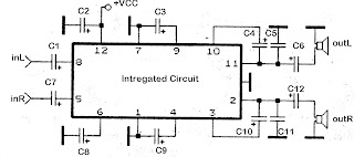
Audio amplifier circuit has a power output of 2 x 2.3 Watt, which uses IC KA2206, KA22061, LA4180, LA4182, LA4183, LA4550, LA4555, LA4558. The required voltage for at least 6 volts to 13 volts DC maximum. Component takes is a ic that I mentioned above one of them, and several capacitors elco.


This Schematics low power amplifier

schematics LA4558

Component Description
C1 = 1uF
C2 = 100uF
C3 = 100uF
C4 = 100uF
C5 = 0.1uF
C6 = 470uF
C7 = 1uF
C8 = 100uF
C9 = 100uF
C10 = 100uF
C11 = 0.1uF
C12 = 470uF
ICs can use the ic which I mention above for each ic datasheet can be seen itself.
[Continue Reading]

Create a electric shock resistant tool

Youve electric shock?? .. Well, .. it was nice to recover all your gout! Sometimes true .. but we often do not touch circuit accidentally in the work that is still connected with line / grid (pln) .. pissed, wants I think we stepped on the stuff ..! patient first. 


Is there any easy way to avoid electric shock in repair work .. can even avoid the occurrence of ESD, if we deal with electronic goods which are sensitive to ESD (PC motherboards, mobile phones, circuit digital etc). you raft just like this series .. used as supply for the solder, when dealing with components which are sensitive to ESD and touch (CMOS IC). the greater capacity of the transformer Ampere. the greater the (good) power which can be handled. The second transformer is identical / similar.
[Continue Reading]

Saturday, November 16, 2013

Volume Controller Equalizer Using LM1036

This volume controller equalizer electronic project is designed using LM1036 DC tone volume controller with volume and balance circuit for stereo applications .An additional control input of the LM1036 allows loudness compensation to be simply effected.

Volume Controller Equalizer Circuit Using LM1036


The four control inputs of the LM1036 volume controller provides control of the bass, treble, balance and volume functions through application of DC voltages from a remote control system or, alternatively, from four potentiometers which may be biased from a zenner regulated supply provided on the circuit.Each tone response is defined by a single capacitor chosen to give the desired characteristic.
[Continue Reading]

Water Softener with NE555

With the intention of Water Softener Circuit is based next to a practice to remove otherwise neutralize the brackish appearing in hose, and shield the pipes next to native soil having the status of well as the washing apparatus before our selves from brackish. Its called dampen softener and its automated circuit using two NE555 timer chips. The cost of parts is near 10$ and its very at ease to build it.

Water Softener Circuit
Water Softener Circuit Schematic
[Continue Reading]

Tips and Tricks on Audio Power Amplifier Circuit

Amplilfier power series from the beginning until now did not experience any changes. Some say this series is good, but the series was good fitting assembly and tested the results are not as we expected.
The problem is usually treble is less subtle, less sound, sound breaking, buzz, middle of the field tested the bass sound is lost. so you do not have to believe what people 100%. The quality amplifier built-up would differ greatly with the amplifier assembly, a series can be the same but the quality will depend on who manufacture it.

Here are a few tricks to try

How to cope with a buzzing sound
Power amplifiers are often used in the field blazer. This circuit is said said person is a bell assembly. But you do not immediately interested in this power, the circuit rather complicated and difficult to understand reflect the intelligence of people who first mendisainnya. In my opinion a great power is the power of simple, inexpensive, easily assembled and rational. You do not need to use expensive components such as the price of tantalum capacitors, power mosfet and the other expensive. This does not determine the quality of the power amp so that we raft. Power of sometimes causing buzzing, to overcome that is by holding the line input jack ground to the ground with 10-22 ohm resistors. So do not just take the ground input from the ground but held first with the R 10 ohms.


How to setting bias trimpot
Rotate the trimpot bias (if any) until the drain current of 50-100mA on each power transistor, in order to avoid defects treble in volume in the top position at 10. The risks are so panassss heatsink! (This setting marks on plate A-AB)

Offset trimpot setting
At the time of input without a signal, turn the trimpot so that the voltage on the speaker offsets actually read 0 volts. If you do not want to bother, use and entrust it with ic type series from Hitachi HA17741 IC brand quality or other! This is the heart of the series, 90-95% of quality is determined from the IC circuit this!

Overcoming the voice
Use pre-amp circuit to increase the signal of at least 2 times. normally and should pre-amp circuit uses IC op-amps with +12 V minimum supply-12V. Raise his mid tone!
If hard you do not want to just use the tone control circuit IC is his mid!
The secret is not in his mid tone alone, but the signal output from the IC op-amps are usually large.

Treble rupture
Excessive treble will damage the power amp, power rather than out even ngedrop. Handle, attach the filter capacitor on the input 1NF power amp to ground to ensure the signal is not disabled. Always use a quality active components such as ICs and transistors, 500 price difference will also be different results.
Use a large cable and short as possible, especially for leg power transistor, and this transistor should be directly soldered to the pcb.

Missing bass in field
Usually power for field use supplay CT 50V 50V transformer, or at least 42V 42V ct. The greater the greater the supply voltage watt channeled though the series is written only 300-400 Watts only. This course uses Elko capacitors with voltage 80-100V. 10.000uF/100V capacitor will be equal to 4X10.000uF/50V and of course voltage capacitor is filled with full / almost full.
Try to use a strong Elko at temperatures of 105 C. Capacitors are strong in supply of more than nominal voltage is written on his body. For example 4700uF/50V 85C capacitor will quickly explode in voltage 51V 85C. And Elko will be strong 105C 4700uF/50V voltage supplied more than 50V at a temperature of 85C. Elco so that it does not quickly explode if given the full voltage, keep its temperature as cold as possible, fan with the cool air.

For speaker
Try using a driver speakers that have a large spool diameter fitted with a suitable size bok. Usually included examples of the parameters / dimensions bok. Size bok bok2 usually larger than that sold in the market. if you force using bok that from this market, use driver type G12-80 (sorry no fear brand called promotion) speakers with bass tones to wall size small. Bok wall should be thick, strong and do not forget glued! Bok who will not be glued with a different sound, especially bass tones, prove it!

Heat Sensor
The form of transistor, the transistor is usually type BD139 MJE340 or it could be located in the center, flanked by a pair of transistors having a certain equal. These transistors must be mounted on the main heatsink to detect the heat generated by power transistors. It acts to lower bias currents at the hot heatsink. So what heatsink and power transistors must be set diposisi hot? Yes objectives nothing to prevent the signal from the defect (in class A or AB), with consequent heat. This class is not necessary and will not be felt if you only want the bass tones only. Goal setting on. AB grade is still crystal clear sound even though the maximum volume positioned rotated (in the middle of the field).
It is unlikely, but its closer.

Large heatsink
Not only electrolytic capacitors are more explosive at high temperatures, power transistors can also break away under stress break the original. For example 2SC5200 transistors have the break voltage of 230Vdc, but if temperaturya high voltage values ​​will break his fall well below this value, resulting in faster transistor is damaged. Use of heatsink and cooling fan is very important not only to reduce the heat, more than it can prevent the transistor from break / damaged and weakened output. Increasingly hot temperatures will be more or less ability. Use of this cooling is expected for the components remain fresh, fit and durability.


Choice Component
Power Transistor
There are so many types and models of these transistors, for example MJ15003 MJ15024-4 and-5 from Motorola, but unfortunately these components are not manufactured by Motorola again but from ON semiconductor. Transistor model jengkol usually stronger in the high temperature, probably due to more airtight. 2SC5200 from Toshiba, this transistor is equal dalamannya Sanken 2SC2922 Korea, and both will break if the temperature is too hot. 2SC2922 Sanken issued tin granules when heated, this weakness, the Japanese technology is better than Korean technology. 2SC3281, this transistor is the most popular and frequently used in professional amplifier, but Toshiba does not produce much, if still there in the market, then it most likely is fake!

Transfomer
There are two models of the transformer which is often used, namely EI model (box / conventional) and the model toroid (ring / donut). Some say the toroid transformer model is better because it has a smaller flux leak, in fact the same. Circuits that are sensitive to this flux is high berpenguatan circuits like pre-amp head and mic pre-amp. The circuit is usually installed horizontally / flat parallel to the structure of a conventional transformer wire so that a series of emails received reverberation is greater. Unlike the model toroid transformer is arranged in a vertical wire their email so that the wires are perpendicular to circuit kits The effect is the flux of the pre-amp kit receive a smaller head. To solve for this flux does not enter the series is by downloading shelding / fortified with non-magnetic plate such as aluminum plate and copper plate / sheet pcb board. Plate is of course connected to ground via a cable. To match the flux in a vertical transmission, the conventional transformer needs to be installed side (the side be side down) so that the arrangement of transformer wire stand upright, this method is often used in built-up POWER2. Voltage 50V 50V CT can be obtained by combining the two transformer 25VCT25V, CT is not used, the foot 25V 50V so that the legs be made only to CT, bringing the total number is 100V or 50VCT50V. It deserves used for pwr amp powerless over 400Watt.

Resistor 5 Watt
Resistor on the power transistor legs are usually valued at 0.5 ohm 5 Watt white square. If we dismantle dalamannya it appears there was a circular aluminum wire. It resembles the inductor, the inductive reactance inductor will be higher when fed a high-frequency fractions so that treble tone will be weakened and deformed. Power required to remove the high notes (treble) of course greater, there is a problem here. The use of R 0.5/5W on its home-based power amplifier ok-ok only. But often do not realize the cause of damage to the speakers and power amplifiers is the high treble tones. Treble is not out but was hit by a pwr amp so arising is hot and damaged. We recommend using common Watt resistor 2 12:47 - 1 ohm parallel 2 so that counted 4 Watt. Or if you use 0:22 ohm 2 Watt Resitor unnecessary because the voltage clamp diparalel quite half (one R 0.5/5W replaced one R 0.22/2W) its ok.

Fuse
Nature damage to semiconductor materials / transistor power amplifier is short, if you use a supply that is high enough then the destruction of these transistors will invite their partners to be damaged as well. In order for the destruction of this transitor congregation not need the installation of fuses. 1.5A per power transistor is considered sufficient. 
[Continue Reading]

Tips for caring power supply units

tips merawat komputerPower Supply on a computer is an energy source that drives the computer you. With power supply, hardware on the computer is given "power" to can work in accordance with their respective functions Power Supply on a computer to work as a flow modifier (Adapter) from AC current into DC. 

Power supply is working on 2 pieces of 5-volt DC voltage and 12 Volt. In a power supply, voltage 12 volt is usually characterized with a yellow cable, while the voltage is 5 Volt is marked with cable red.

PSU schematics

Tips to maintain power supply in order to remain durable

1. Make sure you buy the power supply to suit your computer needs. Buy power supply that is guaranteed quality.

2. Make sure when you install a power supply on your computer already in the correct position. Make a tightening of the socket-outlet power supply to the motherboard, hard drive, CDRom, etc.. If you do the installation is not correct it will be fatal and can be a fire or a short-circuit will occur on your hardware.

3. Check your power supply voltages in the BIOS Hardware Monitor or Hardware Management. Is it permissible range qualified. If it does not fit will usually be marked with red writing.

4. Check the condition of the fan at any time at least 3 months. Or, when you have a problem on your computer such as Hang, Restart and Total death. Clean the fan if necessary and give a lubricant (contact cleaner) in as a fan.

5. Do not put your CPU is too close (mepet) with the wall. Because it would cause air circulation fan should be running with the operation will be disrupted.
[Continue Reading]

Friday, November 15, 2013

Cheap Electronics Component for Amplifier Application

cheap electronics
Cheap electronics component for amplifier application, it is simple to be made for speaker active . The sound quality even this  Mini Amplifier TDA2030 quite satisfactory for a portable audio system.


"The series of Mini Amplifier TDA 2030 "The series of mini amplifie can reproduce the power output of 14 Watt with 8 Ohm speaker load. The series of mini-amplifier can be supplied with ource voltage of 12 volts - 15 volts DC. more details, see the following series of pictures.

cheap electronics

Daftar komponen
Resistor:

- R1: 150KΩ
- R2: 4.7KΩ
- R3: 100KΩ
- R4: 1Ω 1W
- RA/RB: 100KΩ

Capacitor

- C1: 1µF / 25V
- C2: 2.2µF / 25V
- C3: 100nF
- C4: 22µF / 25V
- C5: 100 µF / 25V
- C6: 220nF
- C7: 2200µF / 35V

IC / Dioda

- IC1: TDA2030 or TDA2030a
- D1/D2: IN4002
[Continue Reading]

2SC5200 and 2SA1943 high fidelity power transistor

2SC5200 and 2SA1943 transistor amplifier
Here are two transistors manufactured by Toshiba. 2SC5200 and 2SA1943 transistor pair has been widely applied or used in the amplifier power amplifier because the transistor has a large power, and also not too expensive than other large power transistors. This transistor has the advantage of High breakdown voltage: VCEO = 230 V (min), Suitable for use in 100-W high fidelity audio amplifiers output stage. For more information, please see datasheet below.


Maximum Ratings (Tc = 25°C)


datasheet 2sc5200 and 2sa1943

Electrical Characteristics (Tc = 25°C)


characteristics transistor 2SC5200 and 2sa1943
[Continue Reading]

NJM2035 High Quality Stereo Encoder

High Quality Stereo Encoder with NJM2035


NJM2035 | High Quality Stereo Encoder
This stereo encoder is the perfect solution for those looking for transmitting high quality stereo sound with low cost. This stereo encoder produces crystal clear stereo sound very good and very good channel separation that can match many more expensive stereo encoders that are available in the market.

Its all possible thanks to 38KHz quartz crystal that controls the 19kHz pilot tone, so youll never go back to calibrate or adjust sirkuit.NJM2035 offer superb quality and manufactured by NJR CORPORATION (JRC), a subsidiary of New Japan Radio, a company known as the worlds best manufacturers of high end professional audio semiconductors. This transmitter will work with mono FM transmitter including the TX300 and TX500 are available on our website. The entire series can easily fit on a small "x 1.5" printed circuit board that allows to adjust in a place where space is limited. While building your stereo encoder please take your time and always check with the scheme to ensure that all connections are done correctly.
NJM2035 | High Quality Stereo Encoder


Technical Specifications:
Supply Voltage: 1.2V - 3.6V MAX
Current Draw:> 3mA
Channel Separation: <25 dB
Signal to Noise Ratio: 67 dB
Operation Temperature: -20 - 75 ° C
Frequency Range: 20Hz - 15KHz
Component List:
R 2x 47K
R 1x 10K
R 1x 82K
VR 1x 50K POT
C 1x 33uF
C 1x 10uF
C 3x 100nF (104)
C 1x 100pF (101)
C 1x 10pF (10)
1x IC IC NJM2035
1x XT 38 KHz Crystal


How it Works

Stereo encoder consists of three main stages, pre-emphasis, digital encoder and mixer stages.
Pre-emphasis stage is achieved by using two 47K resistors and two capacitors 1NF. This helps to eliminate noise generated during the FM transmission of your audio signal.
The second stage is built around NJM2035 is a digital encoder. All internal blocks except for two audio amplifiers (pins 1 & 14) which acts as a separator made using digital circuits. The first digital circuit is a 38KHz oscillator generated by using external 38KHz crystal (pin 7), 10pF capacitor (pin 6) and 100pF bypass capacitor (pin 5). After 38KHz frequency generated is then buffered and divided into two 19KHz signals with a 180 degree phase difference. Once it is done two frequencies associated with two time division switching MPX digital alternating, one for each audio channel. Heres the audio channel is switched between each other with a total frequency of 38KHz. If you will be able to slow this frequency to 1Hz per second you will be able to hear that this trick is all but. During the first half of the two you will hear the left audio channel and in the second half the second you hear the right audio channel. Due to the fact that the channels are activated by a rapid frequency of 38KHz per second our brain can not recognize that this channel is really switched on and accept this as a continuous audio signal. At the same time another signal from the 38KHz oscillator is divided half to 19KHz. This signal is called a PILOT tone because it will help the stereo decoder in the receiver to slice MULTIPLEX signal (mixed L and R audio channels) and separate them back to the left and right channel audio.
The third stage is a mixer which consists of 33uF and 100nF capacitors and resistors are 82K and 10K. The role of this circuit is to mix the multiplex subcarrier and pilot signals together. The subcarrier multiplex signal coming out of Pin 9 of IC NJM2035 is the sum and difference of both left and right audio channels are activated at 38Khz. PILOT signal coming out of the pin 8 is the frequency of 19KHz that is used to distinguish what channel is currently switched on and without decoding stereo that will not be possible.
[Continue Reading]

Thursday, November 14, 2013

Regulated Dual 3 Watt White LED Lamp

This project involves constructing an energy efficient dual 3 Watt white LED array that runs on 12VDC at 700mA. The lamp is useful for indoor indirect room lighting. The light that is produced does not flicker and has a regulated brightness from 11V to the maximum operating voltage. The Avago 3W white LEDs are rated at 3 watts (nominal). Never stare directly at this lamp when it is running at full operating power, it is dangerously bright.


Regulated Dual 3 Watt White LED Lamp

Specifications:
  • Nominal operating voltage: 12V DC
  • Nominal operating current: 700 mA
  • Maximum operating voltage: 16V DC
  • Power consumption at 12.0V: 8.4W
  • Minimum voltage for regulated light: 11V DC
  • Leds produce light down to: 6V DC
  • White LED voltage: 3.7V DC each
  • White LED input power: 2.59 W each
  • Voltage across regulator when current becomes regulated: 3.3V DC
Theory:
The lamp is wired as a current loop which includes the power supply, the LED series string and the 700 mA current regulator circuit. The LM317 and 1.8 ohm 5 Watt resistor act as a current regulator that limits the loop current to 700 mA. Two 100nF monoblock capacitors bypasses the LM317 IC.

Construction:
The LEDs and current regulator circuit were mounted on a 3" x 6" piece of blank double-sided circuit board stock. The two LEDs and the LM317 regulator were soldered directly to the circuit board copper using a 200/240W soldering gun. The circuit board should be pre-tinned with solder and soldering should be done quickly to avoid overheating the parts.

The Avago LEDs come in several variations, the part used has an electrically isolated mounting tab, this feature is necessary for preventing a short circuit. If you cant find an LED with an isolated tab, be sure to mount each LED on its own isolated copper board. As of 2012, the specified LEDs are no longer available but there are plenty of other 700mA,3.7V white LEDs available. Just be sure to select one that you can easily solder to and connect to a heat sink.

The first version of this prototype ran too hot, so an aluminum heat sink was bolted to the board near the voltage regulator. Soldering the LM317 tab directly to the circuit board makes the board electrically hot at 1.8V, the board should not be allowed to come into contact with any live conductors. The LM317 may be optionally mounted on an insulated spacer to electrically isolate the board, in this arrangement, a TO-220 heat sink should be directly attached to the LM317.

The two resistors shown in the photo are combined in parallel to make a 1.8 ohm resistance, a single part would be a better choice. The entire circuit board can be mounted inside of a piece of aluminum "U" channel using plastic spacers for electrical isolation. The "U" channel reflects the bright light away from the side.

Use:
Connect this circuit to a 12VDC power supply or other power source such as a solar-charged lead acid battery. Be sure to observe the correct polarity. Look away from the LEDs and apply power. Again, do not stare directly at the LEDs. Prolonged exposure may harm your vision. A switch-mode power supply rated at 12VDC and 1 Amp or more is the most energy-efficient way to power one of these devices from line power. Your author liked this lamp so much that he constructed three of them to run in parallel and light his main electronics work bench.

Parts:
1x LM317 TO-220 case 1A adjustable voltage regulator
1x 1.8 ohm 5W resistor
2x 100nF 35V or higher monolythic capacitor
2x Avago ASMT-MYE2-NMN00 isolated tab 700mA,3.7V warm white LED or equivalent
3"x6" piece of double-sided copper circuit board stock
Miscellaneous wire, solder lugs, termination strips and hardware,
Large aluminum mounting plate, heat sinks if necessary.
[Continue Reading]

Simple 3 Transistor Amplifier

Mini 3 transistor amplifier is a simple amplifier with 50mW power drawn by 3 transitor. The series of three mini-amplifier transistors can be used for loud speaker 8 ohm load. Source voltage required to activate the mini-amplifier can be drawn from the batteries 9V.Rangkaian 3 transistor amplifier is often used in simple portabe audio devices such as radios or small tape recorder. Mini-transistor amplifier circuit 3 is quite simple as shown in the figure below.


Mini Amplifier with 3 Transistor

Mini-transistor amplifier circuit 3 includes type of amplifier OTL (Output Transformer Less). Mini-transistor amplifier circuit 3 is used for output coupling capacitors. Amplifier circuit is simple and suitable when used for audio amplifier experiment.
[Continue Reading]

3 Level Audio Power Indicator

3-Level Audio Power Indicator
This circuit is designed to indicate the power level output of any audio amplifier. Its simple, portable, and displays three power levels can be adjusted to any desired value. For a standard power amplifier hi-fi stereo, the output values ​​suggested are:
  • D5 illuminates at 2W
  • D4 illuminates at 12.5W
  • D3 illuminates at 24.5W
The above values ​​were selected for easy setup, but other options are possible. IC1A is the input buffer, feeding 3 voltage comparators and LEDs drivers by means of a variable DC voltage obtained by R5 and C4 smoothing action. In order to achieve stability of adjustment, the supply of IC1 and trimmers R6 and R7 is reduced and is subject to 5.1V by Zener diode D1.
[Continue Reading]

Wednesday, November 13, 2013

Bass Booster with TL072

The following is megabass circuit schematic (rangkaian megabass) . The megabass circuit is a modified Baxandall tone control with no bass cut and no treble control. It boosts frequencies from about 30Hz to 160Hz can boost by 14dB.

Bass Booster Schematics
Bass Booster with TL072

Note:
The input capacitor can be replaced with a .01uf cap if you wish.
The 10pf capacitor is optional and will start rolling off everything over 15kHz. 5pf will double this to 31kHz.
The tone control requires a low impedence input. If you already have a low impedence input, the input buffer can be removed. However, the output is inverted.
The opamp is not critical. A 4558 would be just fine.
I do not show the parts for the +4.5 reference. Here is the +4.5 voltage divider I used.
IC A4558 Pinning

The A4558 is a monolithic Integrated Circuit designed for dual operational amplifier.

Absolute maximum ratings of A4558 Ap-amp
Supply voltage VCC 20 or ±10 V
Differential input voltage VIND 20 V
Input voltage VIN ±10 V
Power Dissipation PD 300 mW
Operating temperature Topr -45 ~ +85 °C
Storage temperature Tstg -55 ~ +150 °C
[Continue Reading]

Bidirectional Motor Control Using L293 Driver

Using the L293 quadruple high-current half-H driver integrated circuit can be designed a very simple high efficiency motor control. The L293 is designed to provide bidirectional drive currents of up to 1 A at voltages from 4.5 V to 36 V. The L293D is designed to provide bidirectional drive currents of up to 600-mA at voltages from 4.5 V to 36 V.

Bidirectional Motor Control Circuit Diagram


Each output is a complete totem-pole drive circuit, with a Darlington transistor sink and a pseudo-Darlington source. Drivers are enabled in pairs, with drivers 1 and 2 enabled by 1,2EN and drivers 3 and 4 enabled by 3,4EN. When an enable input is high, the associated drivers are enabled and their outputs are active and in phase with their inputs. When the enable input is low, those drivers are disabled and their outputs are off and in the high-impedance state. With the proper data inputs, each pair of drivers forms a full-H (or bridge) reversible drive suitable for solenoid or motor applications.

External high-speed output clamp diodes should be used for inductive transient suppression. In this bidirectional stepper motor controller electronic project VCC1 is logic supply and must me between 4.5 and 7 volts ( typically 5 volt) and VCC2 is the power supply for the motor and must be from VCC1 up to 36 volts.
[Continue Reading]

XM Satellite Radio Vs Sirius for your Auto Sound System Selection

If youre in the market for a new auto sound system you might want to seriously take a moment and consider whether or not you would be benefited by subscribing to either Sirius or XM Satellite Radio. Both of these subscription-based services have something wonderful to offer their subscribers and both of them require specialized equipment in order to operate. This means if you are going to wish to use either service, you will need to have decided which service before you have your auto sound system installed.


XM Satellite Radio Vs. Sirius for your Auto Sound System Selection
It really doesnt matter which of these you choose they each have different features that will appeal to a wide variety of audiences. You will find some wonderful competition among the two not only by way of music radio but also talk radio. If you really love talk radio you really need to subscribe to one of these in order to find a treasure chest of talk radio gems. You will find everything from the mundane to the controversial. From Oprah to Howard Stern exist in the realm of satellite radio, which seems to not only be catching on but also here to stay.

It has been commented on many times that XM Satellite Radio has a strong lead when it comes to subscriptions. This is very true but you should also keep in mind that the new subscribers seem to be leaning more towards Sirius for their satellite radio rather than going with the traditional favorite. Ive checked out the line up and cant see that one has much of a clearly defined lead over the other so I cant give a definitive reason for the massive new subscribers to Sirius or even the phenomenal lead that XM Satellite radio is currently enjoying. Regardless if this is something that might interest you, you really should check out each website and decide for yourself which, if either, is more appealing to you as well as whether that appeal is worth the investment and the monthly subscription fee.

I will say this however: XM Satellite Radio for the moment seems to have much better toys to offer consumers. That being said, Im actually quite surprised that the vast number of new subscribers are going with Sirius rather than XM. Of course, being the gadget geek that I am, I am basing that surprise solely on the fact that XM seems to have much better toys. At the moment XM is offering some really cool gadgets that double not only as XM Satellite Radio receivers but also offer GPS functionality and navigation assistance and controls. Some of these devices even go one step further and play DVDs, CDs, MP3s, among other things.

Believe me, Sirius has a lot to offer its customers as well, Im simply thrilled over select items that can be found at XM that I really havent seen adequate competition for elsewhere. On the level of music, both seem to carry similar genres, lineups, etc. The same holds true for the Talk radio line up. The only major difference I am finding between the two are the gadgets. Even the prices are rather competitive with one another. I see only one other major difference and that is the fact that Sirius offers a lifetime membership that cost about the same as the five-year plan from XM Satellite Radio. The thing to remember however is that the lifetime membership is for the lifetime of the device not the subscriber.

I should also point out that opting for satellite radio more than likely will not eliminate your need for a new auto sound system it may however pose certain requirements for the type of sound system you will be able to choose. One thing I have noticed with both companies is that there are plenty of devices from which to choose. You will have your hands full selecting the right equipment for your auto sound system upon which to enjoy the wonderful sounds that satellite radio will bring to your ears each and every day.
[Continue Reading]

ADSL and DSL Inline Phone Filter

When the ADSL and PSTN works on the same line at the same time, a problem the electronics in a normal telephone for high frequency signals ADSL: ADSL signals can be reduced (with high capacity intercom can be resonances in the phone, impedance mismatch ) and ADSL signals can be heard as the sound on some phones (electronic phone demodulates RF signal is out of range voting frequency noise). Just to keep these systems and stop interfering with each other, it is necessary for the two components of the telephone in your home to separate.

ADSL and DSL Inline Phone Filter Circuit diagram


This is where the filter / splitter comes in. The ADSL POTS splitter / filter allows you to take full advantage of the frequency 1.1 MHz copper line to take, stopping the ADSL and phone systems interfere with each others. An ADSL filter is normally a small plastic box with a short cable that connects to your telephone jack and two outputs, one for your ADSL modem and a telephone. Some filters have an exit by calling them. ADSL filter to the frequency band for each of the outlets, telephone or ADSL to select just the right tire and sending in the socket. The output of the phone is not receiving phone frequencies (from DC to 3.4 kHz) and the output is higher and ADSL freuquencies (above 25 kHz).

For good system performance, it is very important that all your other phone equipment is separated from the ADSL signals using a splitter / filter – This equipment includes telephones, answering machines, “normal” modems, etc., etc.
[Continue Reading]

Tuesday, November 12, 2013

Subwoofer amplifier with 30W output power

hifi amplifier
Amplifier circuit is very suitable for use in subwoofer amplifier system based on IC SI1030G. Amplfier has 30W output with 8 ohm impedance. Supply voltage required minimum of 12 volts and a maximum of up to 22 volts DC.

subwoofer audio amplifier with SI1030DL
Component List :
R1 = 100K
R2 = 1R
C1 = 2.2uF
C2 = 100uF
C3 = 47uF
C4 = 100nF
C5 = 10uF
C6 = 47uF
C7 = 100uF
IC = SI1020GL , SI1030G
[Continue Reading]

15W Stereo audio Amplifier using TDA 4935

15W Stereo audio Amplifier using TDA 4935

TDA4935 2x15W audio amplifier is high quality Siemens IC. The IC can be used in stereo or bridge mode. In stereo mode can deliver 15W Stereo audio Amplifier using TDA 4935 per channel in bridge mode can deliver 30W to an 8 ohm load at the source of 30V. TDA4935 requires very few external components and has an ample supply voltage range. The IC operates in class B and has built-in protection circuits over temperature and overload protection.


Notes :

  • The circuit must be assembled on a good quality PCB.
  • TDA 4935 must be fitted with a proper heat sink.
  • The supply voltage can be anything between 8 to 30V DC.
  • Capacitors C1, C2, C8 are polyester capacitors.
  • Capacitors C3, C4 and C6 are ceramic capacitors while C5 and C9 are electrolytic.
Via : circuitstoday.com

[Continue Reading]

Troubleshooting STR IC Regulator Power Supply


A. Unable to start.
Can be caused by:
  • No start-up voltage supply Vcc or a voltage less than 16V
  • Electrolityc Capacitors supply voltage Vcc filter dry.

  
2. Led indicator blinking
If the supply voltage Vcc examined rocking. This is because the regulator of life and death because OVLO work., Die-protectionist regulators and auto start life over and over. If it is turned off  Electrolityc Capacitors  usually still keep the rest of the cargo.
Can be caused by:

  • Electrolityc Capacitors supply voltage Vcc filter on a pin-4 dry. Replace with a value equal to or slightly larger. - triger UVLO
  • input filter capacitor on pin-1 feed dry behind the declining value - triger OLP
  • Rectifier diode of the switching transformer is damaged (sometimes when examined with avo-meter looks like a still good)
  • cause the supply voltage Vcc drops of the switching transformer (UVLO)
  • Part damage or broken lines on the feedback circuit of the voltage regulator through B to photocoupler - triger OVP
  • Electrolityc Capacitors dry filter voltage B - triger OVP
  • One of the output voltage of the switching transformer secondaries there is a short (over load) - triger OLP
  • Soft start capacitor value decreases - triger OLP

3. Noise arising (noise)
Can be caused by:

  • Transformer windings slack.
  • If there are ceramic capacitors - can sometimes cause interference noise due to its characteristic piezoelectrik like crystal resonator. Replace with film capacitors.

4. When the st-by normal stress. But when the power is on the regulator directly off protectionism no voltage on the secondary this part.  Electrolityc Capacitors  are still storing charge.
Can be caused by:

  • Sensor OVP small value resistor on pin-2 to the ground so that the value of delayed triger to OLP or OCP.
  • Regulator IC is damaged

---------------------------------------------------------------------------------------------------------------------------
Note: Be careful when the regulator is not working. Because of  Electrolityc Capacitors  may still have a charge when turned off.
[Continue Reading]