Showing posts with label lamp. Show all posts
Showing posts with label lamp. Show all posts
Wednesday, November 20, 2013
Automatic Emergency Lamp Circuit
This is an automatic emergency lamp with day light sensing, means it senses darkness/night and turns ON automatically. Similarly it senses day light and turns OFF automatically. A simple emergency lamp which does not require any special equipment; even a multimeter to assemble and use. Any individual who can do a good quality soldering must be able to build this circuit successfully.
This can be easily accommodated in the defunct two 6 watt tube National Emergency Lamp or any PL tube type emergency lamp. The difference will be in the working; it will work non stop for more than 8 hours. Deep discharge is taken care by the LED characteristic and over charge protection is taken care by the fixed voltage regulator.This uses a simple 3Pin fixed regulator which has a built in current limiting circuit.
Simple Emergency Light Circuit Diagram:
 |
| Automatic Emergency Lamp Circuit |
The only required adjustment is the preset which has to be set to ensure the LEDs just light up (it should be left at that position). The 5mm LDR is just mounted on top of the emergency light as shown in the photograph. LDR is used to avoid it lighting up during day time or when the room lights are ON. 2 LEDs are used in series; the dropping resistance is avoided and 2 LEDs light up with current that is required for a single LED, by which energy is saved to a great extent.
This particular circuit has been kept so simple for people who has limited access to components or in other words this is an emergency light that you can build with minimum components. In addition to circuit diagram, He has shared photographs of the prototype he made in National emergency light and a PCB design.

Thursday, November 14, 2013
Regulated Dual 3 Watt White LED Lamp
This project involves constructing an energy efficient dual 3 Watt white LED array that runs on 12VDC at 700mA. The lamp is useful for indoor indirect room lighting. The light that is produced does not flicker and has a regulated brightness from 11V to the maximum operating voltage. The Avago 3W white LEDs are rated at 3 watts (nominal). Never stare directly at this lamp when it is running at full operating power, it is dangerously bright.

Specifications:
The lamp is wired as a current loop which includes the power supply, the LED series string and the 700 mA current regulator circuit. The LM317 and 1.8 ohm 5 Watt resistor act as a current regulator that limits the loop current to 700 mA. Two 100nF monoblock capacitors bypasses the LM317 IC.
Construction:
The LEDs and current regulator circuit were mounted on a 3" x 6" piece of blank double-sided circuit board stock. The two LEDs and the LM317 regulator were soldered directly to the circuit board copper using a 200/240W soldering gun. The circuit board should be pre-tinned with solder and soldering should be done quickly to avoid overheating the parts.
The Avago LEDs come in several variations, the part used has an electrically isolated mounting tab, this feature is necessary for preventing a short circuit. If you cant find an LED with an isolated tab, be sure to mount each LED on its own isolated copper board. As of 2012, the specified LEDs are no longer available but there are plenty of other 700mA,3.7V white LEDs available. Just be sure to select one that you can easily solder to and connect to a heat sink.
The first version of this prototype ran too hot, so an aluminum heat sink was bolted to the board near the voltage regulator. Soldering the LM317 tab directly to the circuit board makes the board electrically hot at 1.8V, the board should not be allowed to come into contact with any live conductors. The LM317 may be optionally mounted on an insulated spacer to electrically isolate the board, in this arrangement, a TO-220 heat sink should be directly attached to the LM317.
The two resistors shown in the photo are combined in parallel to make a 1.8 ohm resistance, a single part would be a better choice. The entire circuit board can be mounted inside of a piece of aluminum "U" channel using plastic spacers for electrical isolation. The "U" channel reflects the bright light away from the side.
Use:
Connect this circuit to a 12VDC power supply or other power source such as a solar-charged lead acid battery. Be sure to observe the correct polarity. Look away from the LEDs and apply power. Again, do not stare directly at the LEDs. Prolonged exposure may harm your vision. A switch-mode power supply rated at 12VDC and 1 Amp or more is the most energy-efficient way to power one of these devices from line power. Your author liked this lamp so much that he constructed three of them to run in parallel and light his main electronics work bench.
Parts:
1x LM317 TO-220 case 1A adjustable voltage regulator
1x 1.8 ohm 5W resistor
2x 100nF 35V or higher monolythic capacitor
2x Avago ASMT-MYE2-NMN00 isolated tab 700mA,3.7V warm white LED or equivalent
3"x6" piece of double-sided copper circuit board stock
Miscellaneous wire, solder lugs, termination strips and hardware,
Large aluminum mounting plate, heat sinks if necessary.
Specifications:
- Nominal operating voltage: 12V DC
- Nominal operating current: 700 mA
- Maximum operating voltage: 16V DC
- Power consumption at 12.0V: 8.4W
- Minimum voltage for regulated light: 11V DC
- Leds produce light down to: 6V DC
- White LED voltage: 3.7V DC each
- White LED input power: 2.59 W each
- Voltage across regulator when current becomes regulated: 3.3V DC
The lamp is wired as a current loop which includes the power supply, the LED series string and the 700 mA current regulator circuit. The LM317 and 1.8 ohm 5 Watt resistor act as a current regulator that limits the loop current to 700 mA. Two 100nF monoblock capacitors bypasses the LM317 IC.
Construction:
The LEDs and current regulator circuit were mounted on a 3" x 6" piece of blank double-sided circuit board stock. The two LEDs and the LM317 regulator were soldered directly to the circuit board copper using a 200/240W soldering gun. The circuit board should be pre-tinned with solder and soldering should be done quickly to avoid overheating the parts.
The Avago LEDs come in several variations, the part used has an electrically isolated mounting tab, this feature is necessary for preventing a short circuit. If you cant find an LED with an isolated tab, be sure to mount each LED on its own isolated copper board. As of 2012, the specified LEDs are no longer available but there are plenty of other 700mA,3.7V white LEDs available. Just be sure to select one that you can easily solder to and connect to a heat sink.
The first version of this prototype ran too hot, so an aluminum heat sink was bolted to the board near the voltage regulator. Soldering the LM317 tab directly to the circuit board makes the board electrically hot at 1.8V, the board should not be allowed to come into contact with any live conductors. The LM317 may be optionally mounted on an insulated spacer to electrically isolate the board, in this arrangement, a TO-220 heat sink should be directly attached to the LM317.
The two resistors shown in the photo are combined in parallel to make a 1.8 ohm resistance, a single part would be a better choice. The entire circuit board can be mounted inside of a piece of aluminum "U" channel using plastic spacers for electrical isolation. The "U" channel reflects the bright light away from the side.
Use:
Connect this circuit to a 12VDC power supply or other power source such as a solar-charged lead acid battery. Be sure to observe the correct polarity. Look away from the LEDs and apply power. Again, do not stare directly at the LEDs. Prolonged exposure may harm your vision. A switch-mode power supply rated at 12VDC and 1 Amp or more is the most energy-efficient way to power one of these devices from line power. Your author liked this lamp so much that he constructed three of them to run in parallel and light his main electronics work bench.
Parts:
1x LM317 TO-220 case 1A adjustable voltage regulator
1x 1.8 ohm 5W resistor
2x 100nF 35V or higher monolythic capacitor
2x Avago ASMT-MYE2-NMN00 isolated tab 700mA,3.7V warm white LED or equivalent
3"x6" piece of double-sided copper circuit board stock
Miscellaneous wire, solder lugs, termination strips and hardware,
Large aluminum mounting plate, heat sinks if necessary.
Thursday, October 3, 2013
Emergency Lamp using IC 555

Emergency Lamp With 555 is one solution for lighting during power outages. With Emergency Lamp Series 555 uses a 12VDC voltage source that can be supplied from the 12V battery. Emergency Lamp 555 Series With these very simple and easy to make because all the components easily available in the market.
Emergency Lamp Series With this 555 can turn on the light 5W-10W. The circuit is built with an astable multivibrator with the IC 555 that is used to mendrive transformer through Q1. For more details can be viewed directly from the series Emergency Lamp With 555 follows.
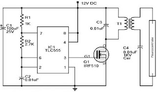 |
| Emergency Lamp Using TLC555 |
Working frequency range of 555 Emergency Lamp With this set of configurations R1, R2 and C2. T1 in series Emergency Lamp With 10V 500mA 555 is a transformer. Secondary part (0-10V) is connected to the Q1 to be given the signal from the multivibrator. Then the primary (0-220V) is connected to the lamp.
Subscribe to:
Posts (Atom)