Showing posts with label battery. Show all posts
Showing posts with label battery. Show all posts
Thursday, December 19, 2013
Low battery detector circuit
You feel confused to detect wether a battery is low or high, or you want to be notified if the battery and has expired , this circuit can detect if a battery has begun to decrease its strength. Circuit is based on LM4250 IC is able to detect if the battery runs out and will issue a notification signal.


Tuesday, December 17, 2013
Battery Level Monitor Circuit
Battery Level Monitor Circuit
This simple circuit can monitor the charging process in 12 Volt Lead Acid battery or Tubular battery. The status of LED indicates whether the battery is accepting charge or not. It also indicates the full charge condition.
This simple circuit can monitor the charging process in 12 Volt Lead Acid battery or Tubular battery. The status of LED indicates whether the battery is accepting charge or not. It also indicates the full charge condition.
 |
| Battery Level Monitor Circuit Diagram |
The circuit can be incorporated in any battery charger like 6 volt, 9 volt, 12 volt etc. The only change needed is replacement of the Zener ZD with appropriate value. That is for 6 volt charger , use 6.1 volt Zener and for 9 volt charger it should be 9.1 volt Zener.
The circuit is based on the switching of two NPN transistors (BC547) to drive the corresponding LED. Zener diode ZD is connected to the base of T1 so as to switch on T1 when the Zener conducts. This happens only when the battery voltage is above 12 volts. Green LED lights when the battery voltage is normal or battery attains full charge. Resistor R1 and Preset VR adjust the base bias of T1 for smooth switching. When T1 conducts, base of T2 will be pulled to ground and T2 turns off and Red LED extinguishes.
When the circuit is connected to the battery before charging the LED indications will be
1. If the battery voltage is above 12 volts (that is the normal terminal voltage of 13.8), Zener conducts and Green LED lights and Red LED remains off.
2. If the battery voltage is below 12 volts, Zener remains non conducting and Green LED remains off and Red LED lights.
3. When the battery is connected to the charger, and if the battery is accepting charge, Green LED goes off and Red LED remains on. When the battery attains full charge, Green LED lights and Red LED goes off.
4. If the battery is not accepting charge, Green LED never lights, even after the prolonged charging. This indicates that the battery is not attaining the normal terminal voltage above 12 volts.
source [link] When the circuit is connected to the battery before charging the LED indications will be
1. If the battery voltage is above 12 volts (that is the normal terminal voltage of 13.8), Zener conducts and Green LED lights and Red LED remains off.
2. If the battery voltage is below 12 volts, Zener remains non conducting and Green LED remains off and Red LED lights.
3. When the battery is connected to the charger, and if the battery is accepting charge, Green LED goes off and Red LED remains on. When the battery attains full charge, Green LED lights and Red LED goes off.
4. If the battery is not accepting charge, Green LED never lights, even after the prolonged charging. This indicates that the battery is not attaining the normal terminal voltage above 12 volts.
Tuesday, November 19, 2013
Battery Charger using LM317 Regulator
 Battery Charger using LM317 Regulator
This Battery Charger is very similar to the universal charger that uses the constant current load. But this is much simpler to build and can be built using only two parties, the LM317 regulator and resistance. The use of diode D is for protection against short circuits. Capacitors C1 and C2 is good voltage regulation. Resistance R2 operates a dummy load when the battery is disconnected. The idea of this magazine is the output current is equal to 1.2 V, divided by the value of R1.
Part List:
LM317
R1 - see the values in table below
R2 - 2.2 kilo-ohms 1/4W
C1,C2 - 47uF/25V, or any value will do, the higher the better
D - 1N4001 or any similar diode at-least 1A rated
Part List:
LM317
R1 - see the values in table below
R2 - 2.2 kilo-ohms 1/4W
C1,C2 - 47uF/25V, or any value will do, the higher the better
D - 1N4001 or any similar diode at-least 1A rated
Monday, November 11, 2013
Make A Virtual Phone Battery
Virtual cell phone battery is a replacement cell phone batteries for those of you who use the phone as a modem. Including myself, who use the phone as a modem HAIER d1200p internet. Why must use this virtual battery. For those who surf hobby "full time" with a phone modem, would know the problem, the battery gets hot and fast reply wasteful even worn out.

This tool is a good solution to keep and care for our cell phones from the possibility of damage from over-charging its battery. I created a virtual battery works as follows: We take the source of its power supply from the USB port because the port is very easy and simple to use and simply provide a standard current source when the phone is online (500-750mA).
The workings of the circuit is as follows: Diodes or diode 2Amper in 5239 this standard to provide a useful addition to the polarity of the voltage which is also a component of protection against misuse. You can just use a 1 Amp diode (IN4002-4007). I use the IN 5239 is due to be durable, more resistant to heat. 4v3 zener diode IN4007 and configured to create a portal voltage of 5V (4.3 + 0.7 volt zener Vin4007) and is useful as a protection system against possible voltage spikes in the event of damage to the CPU. 220nF capacitor as a stabilizer and a substitute for the original battery cells.
The following also 100pF capacitor to smooth and filter the dc current through the diode 5239 which came out of the induction logging. Configuration between zener4v3, IN4007 diode and C 220n form a cell replacement from the actual battery cells, because the battery was actually a capacitor which had a large capacity. You can just remove the three components mentioned above. although it can work fine .
But results are not as good as that use virtual cell (replacement), which certainly was the security which we have to think to avoid the things which are not in want. Making way is to use an old cell phone batteries which have been wasting his cell, a raft of this circuit and the solder terminals on the batteries with the polarity distinguished. Make two holes for the cable to the jack / USB jack.
Determine the length of cable required to taste and use stranded cable with a diameter of at least 1mm. If some type of cell phone batteries are very thin, use a small box for this circuit and connect the two wires to the output voltage again for hp battery casing. Or also if you do not have a former battery casing, use alligator clips to the battery terminal on the phone .. Pin the middle of the virtual pin replacement battery is BSI (Battery Size Insdicator) is useful for HP Nokia.
Phone Battery Charger circuit

The circuit above is a simple circuit to charge phone battery . Charge battery uses an output transformer secondary voltage fast-flowing with 9 Volt 350 mA. First voltage 220/110/120/240 VAC 50/60 Hz , will be reduced to 9 volts,then rectified by 4 diodes 1N4007 and then flowed to light Led voltage power resistor 1 kOhms inhibited. + directly to the battery volltage and voltage - across 47 Ohm resistor and Led charge indicator which is inhibited resistor 100 Ohm then directly to the phone battery.
Saturday, November 2, 2013
Battery Charger based on AVR ATMega 8535
Battery Charger in general can be interpreted as a means to recharge the battery charge. Principles of good charger circuit is capable of providing resources to perform effectively charging the battery, efficient and safe. AVR-Based Battery Charger ATMega 8535 With LCD Display This is an idea that had just emerged from the author.
In AVR-Based Battery Charger design ATMega 8535 With LCD Display is using AVR microcontroller processor charger with ATMega 8535, process the data viewer charger with LCD, a safety from a hot temperature with the temperature sensor LM35 and several buttons for setting the charger. And component power charger Battery Charger Based on AVR ATMega 8535 With LCD Display is a FET. |
| Click to view larger |
Function-Based Battery Charger Part Series AVR ATMega 8535 With LCD Display
ATMega 8535 AVR microcontroller serves as the controlling process of the charger.
Button S1 - S5 as input data charger settings (setting the current, maximum temperature, peak voltage batteries)
LM35 Temperature Sensor function as heat sensors in the battery during charge.
LCD Display function to display data and display settings charger battery charger process measurement data.
FET serves as a power charger that will flow into the battery charging current.
Friday, October 25, 2013
Simple But Reliable Car Battery Tester
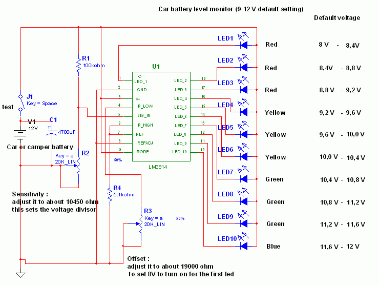
This circuit uses the popular and easy to find LM3914 IC. This IC is very simple to drive, needs no voltage regulators (it has a built in voltage regulator) and can be powered from almost every source. This circuit is very easy to explain: When the test button is pressed, the Car battery voltage is feed into a high impedance voltage divider. His purpose is to divide 12V to 1,25V (or lower values to lower values).
This solution is better than letting the internal voltage regulator set the 12V sample voltage to be feed into the internal voltage divider simply because it cannot regulate 12V when the voltage drops lower (linear regulators only step down). Simply wiring with no adjust, the regulator provides stable 1,25V which is fed into the precision internal resistor cascade to generate sample voltages for the internal comparators. Anyway the default setting let you to measure voltages between 8 and 12V but you can measure even from 0V to 12V setting the offset trimmer to 0 (but i think that under 9 volt your car would not start).
Car Battery Tester Circuit diagram:

There is a smoothing capacitor (4700uF 16V) it is used to adsorb EMF noise produced from the ignition coil if you are measuring the battery during the engine working. Diesel engines would not need it, but Im not sure. If you like more a point graph rather than a bar graph simply disconnect pin 9 on the IC (MODE) from power. The calculations are simple (default)
For the first comparator the voltage is : 0,833 V corresponding to 8 V
* * * * * voltage is : 0,875 V corresponding to 8,4 V
for the last comparator the voltage is : 1,25 V corresponding to 12 V
Have fun, learn and dont let you car battery discharge... ;-)
This solution is better than letting the internal voltage regulator set the 12V sample voltage to be feed into the internal voltage divider simply because it cannot regulate 12V when the voltage drops lower (linear regulators only step down). Simply wiring with no adjust, the regulator provides stable 1,25V which is fed into the precision internal resistor cascade to generate sample voltages for the internal comparators. Anyway the default setting let you to measure voltages between 8 and 12V but you can measure even from 0V to 12V setting the offset trimmer to 0 (but i think that under 9 volt your car would not start).
Car Battery Tester Circuit diagram:
There is a smoothing capacitor (4700uF 16V) it is used to adsorb EMF noise produced from the ignition coil if you are measuring the battery during the engine working. Diesel engines would not need it, but Im not sure. If you like more a point graph rather than a bar graph simply disconnect pin 9 on the IC (MODE) from power. The calculations are simple (default)
For the first comparator the voltage is : 0,833 V corresponding to 8 V
* * * * * voltage is : 0,875 V corresponding to 8,4 V
for the last comparator the voltage is : 1,25 V corresponding to 12 V
Have fun, learn and dont let you car battery discharge... ;-)
author: Jonathan Filippi
e-mail: jonathan.filippi@virgilio.it
e-mail: jonathan.filippi@virgilio.it
Wednesday, October 16, 2013
LM3914 IC based on Simple Battery Tester
 This circuit employs the popular and easy to find LM3914 IC. This kind of IC is quite very simple to drive, requires no voltage regulators (it features a built in voltage regulator) and can be powered from almost every resource.
This LM3914 IC based on Simple Battery Tester is very simple to explain:
Once the test switch is pushed, the Car battery voltage is supply into a high impedance voltage divider. His function is to divide 12V to 1, 25V (or lower values to reduced values). This solution is much better than enabling the internal voltage regulator set the 12V sample voltage to be feed into the internal voltage divider simply because it cannot regulate 12V if the voltage falls lower (linear regulators only step down). Simply wiring with no change, the regulator provides secure 1, 25V which can be fed into the precision internal resistor cascade to create sample voltages to the internal comparators.
In any case the default establishing let you to determine voltages between 8 and 12V however you can measure even from 0V to 12V setting the offset trimmer to 0 (but i believe that below 9 volt your vehicle would not start). There is a smoothing capacitor (4700uF 16V) it is used to adsorb EMF noises produced from the ignition coil if youre testing the battery during the engine working. Diesel engines would not need it, but i am not sure. If you want more a level graph rather than a bar graph simply disconnect pin 9 on the IC (MODE) from power. The calculations are usually simple (default).
Monday, October 14, 2013
Automatic Battery Charger Circuit
Basically the circuit designed above have a very simple way of working, where the circuit is designed so that does not happen short circuit or short circuit between the voltage supply with batteries that will be in-charge.

[Continue Reading]
It is true that if any one wants to try to direct mengghubungkan between supply with batteries then the batteries can be sure will be filled. But the current flowing through a charged battery can not be controlled and if the battery is full, the batteries will be damaged or worn out if it remains on the short circuit condition.
Working Principle Battery Charger
By the time we put an empty battery charging terminals, transistor Q1 will be activated immediately because the current flows through R1 and would trigger a transistor Q1 base. In this condition the flow that would fill the batteries mostly comes from the collector of Q1 is connected directly to the positive terminal of supply. Then during the charging process increases the battery voltage will increase the current flowing in Q2 base via 10 Kohm R5, VR1 and diode D2. VR1 is a component that is used as an initial calibration to determine the exact position in the planning process of switching circuit. For VR1 you can use a trimpot or potensio according to your taste. At the beginning of filling, arrange potensio at position D3 LED indicators on the condition of death, and the current flowing into the collector of Q1 is not too big and not too small.
If the battery is fully charged, the LED indicator will light up automatically because of an increase in voltage on the battery charge will cause the increase of current flowing at the base of transistor Q2 and will terminate the charging cycle due to transistor Q1 having a cut-off due to lack of base current. Why on condition Q1 base current will experience a shortage of this is because almost all the current flowing in R1 10 Kohm will switch to a diode D1 which is logically connected directly with ground experience due Q2 saturated.
.
Component List
1. Resistors: R1 (10 Kohm), R2 (680 ohms), R3 (100 Kohm), R5 (10 Kohm) and VR1 (Potensio / trimpot = 100 Kohm)
2. Diodes: D1 & D2 (IN4002) and D3 (Led)
3. Transistors: Q1 and Q2 (2N3904)
4. 9 volt power supply
By the time we put an empty battery charging terminals, transistor Q1 will be activated immediately because the current flows through R1 and would trigger a transistor Q1 base. In this condition the flow that would fill the batteries mostly comes from the collector of Q1 is connected directly to the positive terminal of supply. Then during the charging process increases the battery voltage will increase the current flowing in Q2 base via 10 Kohm R5, VR1 and diode D2. VR1 is a component that is used as an initial calibration to determine the exact position in the planning process of switching circuit. For VR1 you can use a trimpot or potensio according to your taste. At the beginning of filling, arrange potensio at position D3 LED indicators on the condition of death, and the current flowing into the collector of Q1 is not too big and not too small.
If the battery is fully charged, the LED indicator will light up automatically because of an increase in voltage on the battery charge will cause the increase of current flowing at the base of transistor Q2 and will terminate the charging cycle due to transistor Q1 having a cut-off due to lack of base current. Why on condition Q1 base current will experience a shortage of this is because almost all the current flowing in R1 10 Kohm will switch to a diode D1 which is logically connected directly with ground experience due Q2 saturated.
.
Component List
1. Resistors: R1 (10 Kohm), R2 (680 ohms), R3 (100 Kohm), R5 (10 Kohm) and VR1 (Potensio / trimpot = 100 Kohm)
2. Diodes: D1 & D2 (IN4002) and D3 (Led)
3. Transistors: Q1 and Q2 (2N3904)
4. 9 volt power supply
Saturday, September 28, 2013
LM3914 battery level indicator

Battery level indicator circuit is a circuit that is used to measure the battery voltage / battery. The main components of the battery level indicator circuit is an LM3914 IC. LM 3914 on Circuit battery level indicator is a monolithic IC that detects an analog voltage. And drive the 10 LEDs that produce a linear analog display on a given input voltage.
IC LM3914 is easy to get in the market and not expensive. IC LM3914 battery level indicator on the circuit is often encountered in a series of peak indicator audio signals in analog audio equipment. Battery level indicator circuit consists of IC LM3914, 10 pieces of LED, and a few resistors. The scheme of battery level indicator can be seen below.
IC LM3914 is easy to get in the market and not expensive. IC LM3914 battery level indicator on the circuit is often encountered in a series of peak indicator audio signals in analog audio equipment. Battery level indicator circuit consists of IC LM3914, 10 pieces of LED, and a few resistors. The scheme of battery level indicator can be seen below.
 |
| LM3914 battery level indicator |
In the circuit of the battery level indicator on the supply circuit voltage taken from the battery / batteries through a switch. Didesaimn this circuit will only display the battery level when the switch is pressed. This is intended to save the battery voltage itself.
Monday, September 23, 2013
Nicad Battery charger easy to make
Nicad battery charger , this circuit just use transformer not CT and 3 LEDs lamp. And its very very simple circuit charger . This circuit constant current LEDs to adjust charging current. It uses LEDs that pass a constant current about 15 mA for an applied voltage range of 2 to 18 Volt.
They can be paralleled to give any multiple of 15 mA and they light up when current is flowing. The circuit will charge single cell at 15 , 30 , or 45 mA , or cells in series up to the rated supply voltage limit about 14 Volt.
See schematic below :
 |
| Click to view larger |
Subscribe to:
Posts (Atom)