Showing posts with label control. Show all posts

Sunday, December 15, 2013

Create a Digital Volume Control Circuit

This series is the volume of the digital amplifier That is used on or tone control. This series ic type using DS1669 Digital Pot IC specifically for this volume match. a series of settings used at the middle-class amplifier That small powerless under 50 watts. volum11 components: C1 = 0.1uf Ceramic, IC = IC DS1669 Digital Pot, S1 / S2 = digital swicth Or you can use the series to this one: volum2 The Work: The digital volume control IC uses 9.
Click to view larger.


Required to operate the series voltage regulator is 12 volts. IC1 (555) is very good to work as a flip-flop. Frequency or period can be determined with selecting value of resistor R44, R45 is combined with a capacitor C6. In this series has a 0.3 second period. IC2 is used to Decrease or increase of the calculation. In the series of this mode is used to raise up and down mode is used to Decrease the volume. 
While IC4 and IC3 has a 16-channel, analogue multiplexers, while working as an analog switch. IC3 is used as in the series of level indicator while IC4 is used as potentiometer. After the next power in the on-it, and the switch S1 is pressed to reset. When the switch S2 is pressed, the IC2 and the balance in the form of output legs responded B, C, and D in CMOS IC2. Output B, C and D control line inputs IC2 and IC3, and the chosen one, the 16-channel output, by turning on the analogue. In this series, IC4 is used as the potentiometer is connected to the That resistor 15 (R9 to R23) each of the 16 input pins and resistor / capacitor combination with C2, C3 and R7 to the output. 
Switch S2 is used to raise and switch S3 is used to Decrease the volume. Electrolyte capacitor of 1uF (C4) is used to Prevent the occurrence of noise. While the R8 and the resistor R6 is used to Prevent Tension on the half-supply voltage in order to avoid distortion of the audio signal coming from the preamplifier. Meanwhile, capacitor C2, C3 and resistor R7 is provided to filter the audio. Happy work, hopefully successfully. 

 COMPONENT LIST:

R1, 2, 3, 4 : 560R R16 : 1,5K R45 : 150K R5 : 680R R17 : 3,3K C1 : 0,01uF R6, 8 : 100K R18 : 5,6K C2, 3 : 100nF R7 : 1M R19 : 8,2K C4 : 1uF/50V R9 : 10R R20 : 15K C5 : 100nF R10 : 12R R21 : 33K IC1 : 555 R11 : 42R R22 : 56K IC2 : 74193 R12 : 100R R23 : 1,5M IC3 : CD4067 R13 : 220R R24…R39 : 560R IC4 : CD4067 R14 : 470R R40..R43 : 4,7K IC5 : 7805 R15 : 820R R44 : 330K IC6 N1-N4) : 7407
[Continue Reading]

Wednesday, November 13, 2013

Bidirectional Motor Control Using L293 Driver

Using the L293 quadruple high-current half-H driver integrated circuit can be designed a very simple high efficiency motor control. The L293 is designed to provide bidirectional drive currents of up to 1 A at voltages from 4.5 V to 36 V. The L293D is designed to provide bidirectional drive currents of up to 600-mA at voltages from 4.5 V to 36 V.

Bidirectional Motor Control Circuit Diagram


Each output is a complete totem-pole drive circuit, with a Darlington transistor sink and a pseudo-Darlington source. Drivers are enabled in pairs, with drivers 1 and 2 enabled by 1,2EN and drivers 3 and 4 enabled by 3,4EN. When an enable input is high, the associated drivers are enabled and their outputs are active and in phase with their inputs. When the enable input is low, those drivers are disabled and their outputs are off and in the high-impedance state. With the proper data inputs, each pair of drivers forms a full-H (or bridge) reversible drive suitable for solenoid or motor applications.

External high-speed output clamp diodes should be used for inductive transient suppression. In this bidirectional stepper motor controller electronic project VCC1 is logic supply and must me between 4.5 and 7 volts ( typically 5 volt) and VCC2 is the power supply for the motor and must be from VCC1 up to 36 volts.
[Continue Reading]

Wednesday, October 30, 2013

Digital tone control with MAX5406

The series will I make here is a series regulator of Volume, Bass, and Balance Trable Digital (Tone Control). The core of this circuit is an IC-type output from the Manufacturer Maxim MAX5406, while the IC is an audio processor that comes with the interface switch hit for Tone Control setting above. The circuit scheme is as follows:

The scheme above uses very little supporting components and this makes can be made with a mini size of a matchbox only even if using all SMD components can be reduced in size by half for this time I will only give a simple layout made​​, following picture:

layout components


[Continue Reading]

Monday, October 28, 2013

Guitar Control Circuit Diagram

Guitar Control Circuit DiagramGuitar Control Circuit Diagram

Device purpose:

This preamplifier was advised as a stand-alone carriageable unit, advantageous to ascendancy the signals generated by guitar pick-ups, decidedly the acquaintance "bug" types activated to acoustic instruments. Obviously it can be acclimated with any blazon of apparatus and pick-up.

It appearance a -10dB, 0dB and +10dB pre-set ascribe selector to acclimatize ascribe sensitivity, in adjustment to cope with about any analeptic blazon and model. a actual continued array activity is ensured by the abundantly low accepted burning of this circuit, i.e. beneath than 800µA.

Circuit operation:

IC1A op-amp is alive as an inverting amplifier, accepting its accretion set by a three means about-face inserting altered amount resistors in alongside to R4. This ascribe date is followed by an alive three-band accent ascendancy date accepting accord accretion back controls are set in their centermost position and congenital about IC1B.

[Continue Reading]

Saturday, October 26, 2013

3 Band Tone Control with LF351

3 Band Tone Control circuit uses an op-amp as an amplifier end. Tone Control circuit is a regulator of tone bass, midrange and treble or 3 band called because it can set the three tones. Filter circuit is applied to the series of "Tone Control 3 band" This type baxandal like the title of this article. 

Results filtering regulator tone or tone control baxandal type is good, because there is no signal level is wasted directly into the ground. Range frequency tones generated from Tone Control 3 band was determined by the configuration of the R and C of the filter section baxandal. As an amplifier on Tone Control The set of three band use traditional IC LF351 has slewrate high and high input impedance. For more details, series 3 Band Tone Control as follows.

Figure Series 3 Band Tone Control

3 band tone control

3 Band Tone Control circuit above using LF351 Op-Amp is used to strengthen the signal after filtering by the filter process baxandal. Level tone Bass, Midrange and Treble settings are determined by potensio R1, R2 and R3. Frequency filter in the circuit above baxandal to 50 Hz bass tone, tone Midrange 1 KHz and 10 KHz for Treble tone.
[Continue Reading]

Saturday, September 28, 2013

TDA2030 complete tone control

TDA2030 complete tone controlAt this time I present a series of amplifiers that use IC TDA2030, but this series is equipped with a tone control. Tone controls include Bass, Treebel, and Volume. Power amplifier and tone control has been put together in a single PCB.


As well as its power supply circuit was also used as one with the power amp, and tone control. Making it easier in the installation and will look neat.


Schematics
Layout PCB

PCB design

This amplifier is a mono amplifier type, can be modif for guitar amplifiers. If not coupled amplifier (mic preamp) then you must deactivated potensio treble and bass, why? because if not using a mic preamp and still maintain potensio treble and bass sound input (input) from the guitar will not or the maximum discharge is not tight on the speakers. So you must deactivated a way to decide which directly connected capacitor with the tone control circuit, and capacitor were connected directly to potensio volume and input jack.


[Continue Reading]

Friday, September 27, 2013

Digital control system applications

Digital Control System is a branch of the control system with continuous time processes in the region associated with the digital controller as the controller of the control elements that control systems and computing discrete time. Depending on requirements, a digital controller can be shaped microcontroller and ASIC to a standard desktop computer. Because the digital computer system is discrete, then the Laplace transform is used in the control system is replaced with the Z-transform. Therefore, you must understand about the concept of continuous time and discrete time concept.


Digital Control system applications
Flow Chart - Digital Control system applications

Digital computer also has a limited precision (See quantization) extra care needed to ensure that errors in the coefficients, A / D conversion, D / A conversion, etc. do not produce unwanted effects or planned.

The application of digital control can easily be done when used in a feedback form. Since the creation of the first digital computer in the early 1940s the price of digital computers has dropped significantly. The reason this is one of the many reasons for the application of digital control systems for the control of the control system. Other reasons:

Flexibile: easy to configure and reconfigure through software
* Scalable: can be set up programs tailored to the limits of memory or storage space at no extra cost
* Adaptable: program parameters can be changed with the times
* Static operation: digital computers are much more susceptible to environmental conditions rather than of capacitors and inductors
[Continue Reading]

Friday, September 13, 2013

DC Motor Speed Control using PWM

DC Motor Speed Control using PWMDC Motor Speed Control using PWM
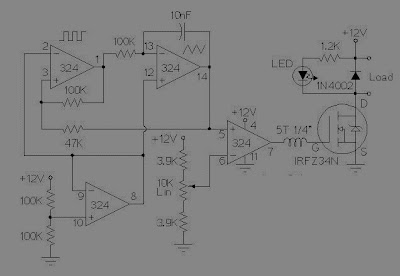


The so-called PWM or Witdh modulation is a technique often used to control a load, for example, is the control of DC motor speed PWM techniques are used frequently.


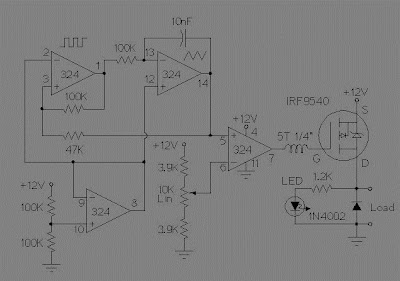
Usually to make a simple PWM (for practice or the introduction PWM) fans to use some of the facts of the op-amp circuit, which consists of Schmitt Trigger circuit, the integrator and comparator.


DC Motor Speed Control using PWM

Schmitt Trigger function that produces a square wave will become the sawtooth wave or integrator is also called common rail and the ramp compared to a reference voltage that can change a lot of stress. So the result is a PWM output.


DC Motor Speed Control using PWM

These two schemes are variations of different circuit PWM. The diagrams are for 12V operation and there are upper (ground) and low side (+12 V common) versions. The version of the lower circuit uses an N-channel FET, the high-side version of the circuit uses a P-channel FET. N channel devices tend to handle more current P-channel devices, which are also less expensive. The version of the high side of the circuit is useful when a portion of the load must be grounded.


This circuit can change a fairly high amount of current, a MOSFET IRFZ34N can handle over 35 Amps if connected to an adequate heat sink. Higher power FETs, such as IRF1010Z IRFZ48N or can be substituted if even larger currents are required. It is also possible to connect multiple FETs in parallel even more current capacity. Always use thermally conductive grease between the FET and the heat sink, and remember that the heatsink is under stress.


Inductive loads (motors) may require special care because it can generate large voltage spikes that can damage the MOSFET. Replacing a 1N4002 fast recovery diode can help absorb the recoil reverse voltage when driving an inductive load like a motor. If you use these circuits to experiment with electric vehicles, be sure to install a circuit breaker in series with the battery, the switch should be easy to reach by the driver. This is especially important given the fact that when non-MOSFETs, is often cut, leaving the engine running at full speed

[Continue Reading]