Showing posts with label 555. Show all posts
Showing posts with label 555. Show all posts
Tuesday, November 19, 2013
Simple Metal Detector Using 555 Timer
This metal detector electronic project schematic circuit is designed using a simple 555 timer integrated circuit . As you can see in the schematic circuit , this metal detector electronic project requires few external electronic parts . This circuit detects metal and also magnets.
Metal Detector with 555 Timer Circuit Daigram

When a magnet is brought close to the 10mH choke, the output frequency changes. This metal detector project can be powered from a power supply that can provide an output DC voltage between 6 an 12 volt . If a metal is closer to the L1 coil , will produce a change of output oscillation frequency, that will generate a sound in the 8 ohms speaker
Metal Detector with 555 Timer Circuit Daigram

Wednesday, October 30, 2013
Police Sirine Circuit with IC 555
The series of police sirens with 555 ic this is a series of sirens that utilizes two IC 555 as a pulse generator and producing shrill voice.

Both ic 555 respectively build the astable multivibrator circuit and generate output signals with different frequencies. It is intended to be used as one of the high frequency generator or a screeching sound and the other as a regulator of the swing from last shrill voice. If we observe the working principle of this circuit is very similar to a series of modulation fm. Where the shrill sound signal likened to a high frequency signal from the oscillator circuit and control signal swing is the wail of the information signal or input signals that will transmit. This is consistent with the shape of the output signal associated with the loudspeaker, which has an output signal frequency changes in the form of regular meetings wave tenuous.
Actually a series of sirens could be simpler than if you use a 556 IC which is a dual multivibrator or equal to two pieces of IC 555. IC 556 has two multivibrator circuit menfaatkan so you can meet the workflow of this siren sound-producing circuit. Or you can also make it by using a combination of multiple transistors. And it could be you do remember the oscillator circuit can be easily made with transistors.
Appropriate image above then:
R1, R2, and C1 is a determinant of the frequency of the signal generated by IC1
R3, R4 and C3 is a determinant of the signal frequency whine
Signals generated by IC1 IC2 pin 5 connected to the control signals intended for the resulting shrieks
Screeching sound signal will swing to follow the control of the output signal IC1
You can do experiments in order to gain more understanding of police sirens this circuit by changing the value of some critical components such as the frequency of R1, R2, R3, R4, C1 and C3.
Thursday, October 3, 2013
Emergency Lamp using IC 555

Emergency Lamp With 555 is one solution for lighting during power outages. With Emergency Lamp Series 555 uses a 12VDC voltage source that can be supplied from the 12V battery. Emergency Lamp 555 Series With these very simple and easy to make because all the components easily available in the market.
Emergency Lamp Series With this 555 can turn on the light 5W-10W. The circuit is built with an astable multivibrator with the IC 555 that is used to mendrive transformer through Q1. For more details can be viewed directly from the series Emergency Lamp With 555 follows.
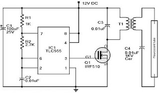 |
| Emergency Lamp Using TLC555 |
Working frequency range of 555 Emergency Lamp With this set of configurations R1, R2 and C2. T1 in series Emergency Lamp With 10V 500mA 555 is a transformer. Secondary part (0-10V) is connected to the Q1 to be given the signal from the multivibrator. Then the primary (0-220V) is connected to the lamp.
Thursday, September 19, 2013
Police Lights Circuit with 555 and 4017 IC
This circuit uses a 555 timer which is setup to both runn in an Astable operating mode. This generates a continuous output via Pin 3 in the form of a square wave. When the timers output changes to a high state this triggers the a cycle on the 4017 4017 decade counter telling it to output the next sequential output high. The outputs of the 4017 are connected to the LEDs turning them on and off.
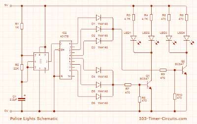 |
| Police Lights Circuit Schematic |
Subscribe to:
Posts (Atom)