Showing posts with label to. Show all posts
Showing posts with label to. Show all posts
Saturday, December 14, 2013
Frequency to Voltage Converter Circuit
IC LM2917 Frequency to Voltage Converter
IC LM2917 IC chip is designed specifically as a Frequency to Voltage Converter or Frequency to Voltage converter. In its use to applications Frequency to Voltage Converter IC LM2917 requires few external components.
There are several examples of applications of Frequency to Voltage Converter IC LM2917 datasheet that is included in the LM2917 IC. In this article series Frequency to Voltage Converter IC also taken from the LM2917 datasheet. The advantages of single chip LM2917 Frequency to Voltage Converter is able to provide instantaneous volt output o at time of frequency change 0 Hz. Very easy to apply in measuring the output frequency with the formulation of single-chip Frequency to Voltage Converter VOUT = FIN x VCC x R1 x C1.Then the single-chip LM2917 Frequency to Voltage Converter This configuration requires only the RC only in frequency doubling. And has an internal zener regulator to aimlessly accuracy and stability in frequency-to-voltage conversion process.
Application circuit Figure IC LM2917 as Frequency to Voltage Converter

Feature-owned single-chip LM2917 Frequency to Voltage Converter
Reference to ground directly with variable reluctance
Op Amp / Comparator with transistor output
50 mA maximum output currents for application directly to the load
Frequency doubling for low ripel
Buid in zener
Linear output ± 0.3%
Application single chip LM2917 Frequency to Voltage Converter
Frequency to Voltage Converter
Rotation speed sensor applications
Speedometer
Tachometer
Cruise Control
Cluth Control
And other applications associated with the measurement of rotation speed or frequency measurements.

Wednesday, November 20, 2013
3V to 40 Volt DC Converter Circuit
Switching regulator subsystems intended for use as dc to dc converters. 3V to 40 Volt DC Converter circuit | The use of switching regulators is becoming more pronounced over that of linear regulators because the size reductions in new equipment designs require greater conversion efficiency. Another major advantage of the switching regulator is that it has increasednapplication flexibility of output voltage. The output can be less than, greater than, or of opposite polarity to that of the input voltage.

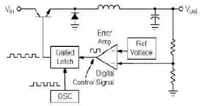
The MC34063 series is a monolithic control circuit containing all the active functions required for dc to dc converters. This device contains an internal temperature compensated reference, comparator, controlled duty cycle oscillator with an active peak current limit circuit, driver, and a high current output switch. This series was specifically designed to be incorporated in step–up, step–down and voltage–inverting converter applications. These functions are contained in an 8–pin dual in–line package.
· Wide Input Voltage Range 3 V to 40 V
· Precision Internal Reference 2%
· High Output Switch Current Up to 1.5 A
· Short-Circuit Current Limiting
· Adjustable Output Voltage
· Low Standby Current
· Oscillator Frequency Up to 100 kHz
Friday, November 1, 2013
1 3V DC to 12 2V DC Regulator Power Supply
Power supply circuit to generate output below were variations between 1.3V DC to 12.2V DC with 1A current.
In addition, the power supply circuit is also equipped with over-current protection or shield against belebih flow. Power supply circuit is very simple, but the quality is quite good, made her basiskan regulator IC LM723 is a pretty legendary.
In addition, the power supply circuit is also equipped with over-current protection or shield against belebih flow. Power supply circuit is very simple, but the quality is quite good, made her basiskan regulator IC LM723 is a pretty legendary.

Description:
R2 to set the output voltage. The maximum current is determined by R3, over-current protection circuit inside the LM723 to detect the voltage on R3, if it reaches 0.65 V, the voltage output will be off her. So the current through R3 can not exceed 0.65 / R3 although output short-circuit in his.
C3 and C4 are ceramic capacitors, as much as possible directly soldered to the PCB, this is because the LM723 is prone to oscillation that is not cool.
LM723 works with 9.5V input voltage to 40 V DC and the LM723 can generate its own current of 150mA when the output voltage is not more than 6-7V under input voltage.
Specifications:
Output (value estimated):
Vmin = (R4 + R5) / (R5 * 1.3)
Vmax = (7.15 / R5) * (R4 + R5)
Imax = 0.65/R3
Max. Power on R3: 0.42/R3
Min. DC Input Voltage (pin 12 to pin 7): Vmax + 5
Component List:
B1 40V/2.5A
C1 2200uF (3300uF even better)
C2 4.7uF
C3 100nF
C4 1NF
C5 330nF
C6 100uF
Green LED D1
D2 1N4003
F1 0.2A F
F2 2A M
IC1 LM723 (in a DIL14 plastic package)
R1 1k
R2 Pot. 5k
R3 0.56R/2W
R4 3.3k
R5 4.7k
S1 250V/1A
T1 2N3055 on a heatsink 5K / W
TR1 220V/17V/1.5
source [link]
Saturday, October 26, 2013
RS232 to RS485 Circuit
The new archetypal of RS485 advocate overcomes the RTS controlled botheration accomplished by our chargeless design. However, to do that requires a microprocessor, so there is a greater complication to the design. We advertise this unit, although currently we are attached our sales to barter who can pay by coffer alteration – which in absoluteness is bounded Australian companies.
This architecture has been almost agitation free, and if you crave quantities we can acclimate the adapter pinout to clothing your appliance – about again the accessory will no best fit the simple little D25 case in which you see it pictured.
 |
| Click image to view larger RS232 to RS485 Circuit |
* Data (vs RTS) controlled – does not rely on PC handshake timing
* DB25 RS232 connector compatible with PC
* TxD and RxD translated from RS232 to RS485
* Direction of transmission controlled by Data
* Handshake loop the PC connection so it works with all software
* RS485 signals output on D9 male with lots of Ground pins
* Indicator LED(s) to show communications traffic
* Line powered – powered by RS232 handshake lines
* RS485 Termination resistor not included
* Pullup/Pulldown resistors on RS485 to establish line-idle condition
* Baud rate is dipswitch selectable 1200 – 115.2k
Saturday, October 19, 2013
Voltage to frequency converter

Changing the voltage to frequency scale in the design of an electronic device is sometimes necessary. The series of articles voltage to frequency converter with the XR 4151 is one answer. Voltage to Frequency converter circuit with the XR 4151 is the idea of time in college, when there are projects to create a tool to hatch chicken eggs.
It will be my neighbor also write articles incubators chicken egg-based microcontroller AT89C2051. Maybe there are friends who still remember to this project. Back to the topic of voltage to frequency converter circuit with the XR 4151. IC XR 4151 is a major component of voltage to frequency converter (Voltage to Frequency Converter).
It will be my neighbor also write articles incubators chicken egg-based microcontroller AT89C2051. Maybe there are friends who still remember to this project. Back to the topic of voltage to frequency converter circuit with the XR 4151. IC XR 4151 is a major component of voltage to frequency converter (Voltage to Frequency Converter).

From voltage to frequency converter circuit with XR 4151 on the input signal circuit is a DC voltage level. IC XR4151 on voltage to frequency converter circuit serves to convert the voltage level coming into form in the development of the frequency change, where the output frequency range of voltage to frequency converter with the XR 4151 is proportional to the voltage level input voltage to frequency converter circuit with this 4151 XR.
Saturday, October 5, 2013
Mono to Stereo Audio Signal Circuit Converter
This circuit is used to convert a mono audio signal into a stereo signal that can be panned between the left and right channel by a 0-10V control signal, it is intended for analog synthesizer systems.
 |
| Circuit Convert Mono to Stereo Audio Signal Schematic |
Tuesday, October 1, 2013
6 to 12 Volt Power Supply Inverter
This inverter circuit can provide up to 800mA of 12V power from a 6V supply. For example, you could run 12V car accessories in a 6V (British?) car. The circuit is simple, about 75% efficient and quite useful. By changing just a few components, you can also modify it for different voltages.
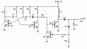
Part List:
R1, R4 2.2K 1/4W Resistor
R2, R3 4.7K 1/4W Resistor
R5 1K 1/4W Resistor
R6 1.5K 1/4W Resistor
R7 33K 1/4W Resistor
R8 10K 1/4W Resistor
C1,C2 0.1uF Ceramic Disc Capacitor
C3 470uF 25V Electrolytic Capcitor
D1 1N914 Diode
D2 1N4004 Diode
D3 12V 400mW Zener Diode
Q1, Q2, Q4 BC547 NPN Transistor
Q3 BD679 NPN Transistor
L1 See Notes
MISC Heatsink For Q3, Binding Posts (For Input/Output), Wire, Board
[Continue Reading]
Part List:
R1, R4 2.2K 1/4W Resistor
R2, R3 4.7K 1/4W Resistor
R5 1K 1/4W Resistor
R6 1.5K 1/4W Resistor
R7 33K 1/4W Resistor
R8 10K 1/4W Resistor
C1,C2 0.1uF Ceramic Disc Capacitor
C3 470uF 25V Electrolytic Capcitor
D1 1N914 Diode
D2 1N4004 Diode
D3 12V 400mW Zener Diode
Q1, Q2, Q4 BC547 NPN Transistor
Q3 BD679 NPN Transistor
L1 See Notes
MISC Heatsink For Q3, Binding Posts (For Input/Output), Wire, Board
source:LINK
Monday, September 23, 2013
Nicad Battery charger easy to make
Nicad battery charger , this circuit just use transformer not CT and 3 LEDs lamp. And its very very simple circuit charger . This circuit constant current LEDs to adjust charging current. It uses LEDs that pass a constant current about 15 mA for an applied voltage range of 2 to 18 Volt.
They can be paralleled to give any multiple of 15 mA and they light up when current is flowing. The circuit will charge single cell at 15 , 30 , or 45 mA , or cells in series up to the rated supply voltage limit about 14 Volt.
See schematic below :
 |
| Click to view larger |
Sunday, September 22, 2013
Voltage to frequency converter
Changing the voltage to frequency scale in the design of an electronic device is sometimes necessary. The series of articles voltage to frequency converter with the XR 4151 is one answer. Voltage to Frequency converter circuit with the XR 4151 is the idea of time in college, when there are projects to create a tool to hatch chicken eggs.
It will be my neighbor also write articles incubators chicken egg-based microcontroller AT89C2051. Maybe there are friends who still remember to this project. Back to the topic of voltage to frequency converter circuit with the XR 4151. IC XR 4151 is a major component of voltage to frequency converter (Voltage to Frequency Converter).
It will be my neighbor also write articles incubators chicken egg-based microcontroller AT89C2051. Maybe there are friends who still remember to this project. Back to the topic of voltage to frequency converter circuit with the XR 4151. IC XR 4151 is a major component of voltage to frequency converter (Voltage to Frequency Converter).
From voltage to frequency converter circuit with XR 4151 on the input signal circuit is a DC voltage level. IC XR4151 on voltage to frequency converter circuit serves to convert the voltage level coming into form in the development of the frequency change, where the output frequency range of voltage to frequency converter with the XR 4151 is proportional to the voltage level input voltage to frequency converter circuit with this 4151 XR.
Wednesday, September 11, 2013
12V to 20V DC Converter Circuit
100 Watt 12V to +/- 20V DC Converter Circuit
[Continue Reading]
DC To DC Converter circuit used to be an convert voltage DC to DC with different concepts. DC to DC converter circuit +12 V to + /-20V is working to change the battery voltage from 12V DC to 20V DC voltage symmetrical. DC to DC converter circuit is often applied to the power amplifier udio on car audio systems. DC to DC converter circuit uses a TL494 IC as power plsa for the converter.
TL494 IC is a PWM controller with an adjustable frequency from 40-60Hz through a potentiometer. Then from the TL494 PWM signal is given to the driver MOSFET inverter TPS2811P to be given to the power inverter with 2 units of MOSFET transistors. Circuit details can be seen in the figure following the DC to DC converter.DC To DC converter circuit +12 V To + / - 20V
 |
| Click to View Larger |
List Components DC To DC Converter +12 V To + / - 20V
- R1, R2 = 10
- R3, R4, R6, R7 = 1k
- R5 = 22k
- R8 = 4.7k
- R9 = 100k
- C1, C2 = 10000uF
- C3, C6 = 47 u
- C4 = 10U
- C5, C7, C14 = 100n
- C8, C9 = 4700u
- C12 = 1N
- C13 = 2.2u
- U1 = TL494
- U2 = TPS2811P
- Q1, Q2 = FDB045AN
- D1-D4 = 1N5822
- D5 = 1N4148
- FU1 = 10A
- L1 = 10U
- L2 = ferrite BEAD
- RV1 = 2.2k
- RV2 = 24k
- T1 = TRAN-3P3S
DC To DC converter circuit +12 V To + / - 20V is capable of supplying up to 100W and can power supplying currents up to 3A. In making DC To DC Converter +12 V To + / - 20V has to be careful and cautious because there are parts of DC To DC Converter +12 V To + / - 20V in the form of an AC circuit.
Subscribe to:
Posts (Atom)