Showing posts with label ic. Show all posts
Showing posts with label ic. Show all posts
Wednesday, December 18, 2013
Schematic Power Amplifier with IC AN7117
*notif : this circuit is mono amplifier
Schematic circuit power amplifier AN7117 below :
 |
| Click image to view Enlarge |

Monday, December 16, 2013
100 Watt Power amplifier with IC TDA1514
Power Amplifier TDA1514 , this power use the IC TDA1514 , minimum require voltage 12 Volt and maximum voltage 30 volts DC. Power output maximum 100 Watt mono with 8 ohms impedance. this circuit is High output power amplifier with IC. See schematic below :

Tuesday, November 12, 2013
Troubleshooting STR IC Regulator Power Supply
A. Unable to start.
Can be caused by:
- No start-up voltage supply Vcc or a voltage less than 16V
- Electrolityc Capacitors supply voltage Vcc filter dry.
2. Led indicator blinking
If the supply voltage Vcc examined rocking. This is because the regulator of life and death because OVLO work., Die-protectionist regulators and auto start life over and over. If it is turned off Electrolityc Capacitors usually still keep the rest of the cargo.
Can be caused by:
- Electrolityc Capacitors supply voltage Vcc filter on a pin-4 dry. Replace with a value equal to or slightly larger. - triger UVLO
- input filter capacitor on pin-1 feed dry behind the declining value - triger OLP
- Rectifier diode of the switching transformer is damaged (sometimes when examined with avo-meter looks like a still good)
- cause the supply voltage Vcc drops of the switching transformer (UVLO)
- Part damage or broken lines on the feedback circuit of the voltage regulator through B to photocoupler - triger OVP
- Electrolityc Capacitors dry filter voltage B - triger OVP
- One of the output voltage of the switching transformer secondaries there is a short (over load) - triger OLP
- Soft start capacitor value decreases - triger OLP

3. Noise arising (noise)
Can be caused by:
- Transformer windings slack.
- If there are ceramic capacitors - can sometimes cause interference noise due to its characteristic piezoelectrik like crystal resonator. Replace with film capacitors.
4. When the st-by normal stress. But when the power is on the regulator directly off protectionism no voltage on the secondary this part. Electrolityc Capacitors are still storing charge.
Can be caused by:
- Sensor OVP small value resistor on pin-2 to the ground so that the value of delayed triger to OLP or OCP.
- Regulator IC is damaged
---------------------------------------------------------------------------------------------------------------------------
Note: Be careful when the regulator is not working. Because of Electrolityc Capacitors may still have a charge when turned off.
Tuesday, November 5, 2013
Stereo Audio Amplifier with IC TEA2024

The circuit above is based on IC TEA2024, package IC is SIP2-10 and manufactered by THOMSON. Circuit above can be applied anywhere as long as the speaker must be required , do not use powered speakers, it will make this circuit of hot , especially on the IC. So the use of powered speakers with the power output of this circuit.
Technical Information :Minimum voltage : 6 Volts DCMaximum voltage: 18Volts DCPower Output : 2 x 7 WattsImpedance : 4 OhmsCurrents : 35 mA
Monday, November 4, 2013
0 4W power amplifier with 5G37 IC
This circuit requires a voltage of 6-12 Volts. To have a good quality of this series with the voltage necessary suplly good too. The definition of good that is filtered and does not release much ripple voltage and using large-capacity condenser elco issued for the bass is strong enough.
See below this circuit :
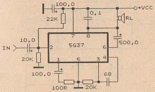
Datasheet IC 5G31A
Vcc = 6-12 V
Pout = 0,4 W
RL = 8 Ohm
Ft = 40-17 Khz
Icco = 15 mA
Package = TABS1-14
Manufactered = China
Saturday, November 2, 2013
Audio amplifier circuit with IC STK0039 good quality amplifier

Although the output of which was issued in this circuit only 35watts maximum, but th esound can be issued harsh , loud , and clear. If the voltage is fit and clean , how to assembly , components are good , the right speakers , this circuit will definitely make a sound that good to hear the ear.
See audio amplifier circuit below :

Technical Information :Vcc Max = 45VVcc TYP = 30VPo = 35WRL = 8OhmIcco TYP = 40mAIcco Max = 80mAI Max = 10A

The amplifier can use to : tuner , subwoofer surround amplifier , surround amplifier , subwoofer system , car amplifier , PC amplifier , DVD/CD amplifier , Room amplifier . Because this amplifier good quality amplifier circuit.

Wednesday, October 30, 2013
Police Sirine Circuit with IC 555
The series of police sirens with 555 ic this is a series of sirens that utilizes two IC 555 as a pulse generator and producing shrill voice.

Both ic 555 respectively build the astable multivibrator circuit and generate output signals with different frequencies. It is intended to be used as one of the high frequency generator or a screeching sound and the other as a regulator of the swing from last shrill voice. If we observe the working principle of this circuit is very similar to a series of modulation fm. Where the shrill sound signal likened to a high frequency signal from the oscillator circuit and control signal swing is the wail of the information signal or input signals that will transmit. This is consistent with the shape of the output signal associated with the loudspeaker, which has an output signal frequency changes in the form of regular meetings wave tenuous.
Actually a series of sirens could be simpler than if you use a 556 IC which is a dual multivibrator or equal to two pieces of IC 555. IC 556 has two multivibrator circuit menfaatkan so you can meet the workflow of this siren sound-producing circuit. Or you can also make it by using a combination of multiple transistors. And it could be you do remember the oscillator circuit can be easily made with transistors.
Appropriate image above then:
R1, R2, and C1 is a determinant of the frequency of the signal generated by IC1
R3, R4 and C3 is a determinant of the signal frequency whine
Signals generated by IC1 IC2 pin 5 connected to the control signals intended for the resulting shrieks
Screeching sound signal will swing to follow the control of the output signal IC1
You can do experiments in order to gain more understanding of police sirens this circuit by changing the value of some critical components such as the frequency of R1, R2, R3, R4, C1 and C3.
Tuesday, October 22, 2013
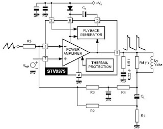
Vertical IC Configuration
Various kinds of vertical out IC configuration. Ac coupling -connect from the yoke deflection output to a coil connected directly. Dc coupling - connected the output to the coil through a capacitor deflectioan yoke. Electrolityc Capacitors (usually worth 1000u/35v). This configuration requires two kinds of voltage (the voltage mirror plus-minus). Dc input coupling using diffferential - uses 2 input from the driver IC.
 |
| Vertical IC Configuration AC Coupling |
 |
| Vertical IC Configuration DC Coupling |
Monday, October 21, 2013
Audio amplifier with IC AN7522 AN7523 and TDA2616

The series of amplifiers that are used on the television audio, amplifier used amplifier ICs, including the IC:
• AN7523• AN7522
• TDA2616
Third series of the function with the same system, namely BTL (Bridge Transformer Less). By using such configuration we get several advantages, namely no use coupling capacitors or coupling transformers.
Block diagram of circuit in the IC AN7522, AN7523 and TDA2616 as in the image below :
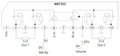 |
| Schematic AN7522 |
 |
| AN7523 amplifier schematic |
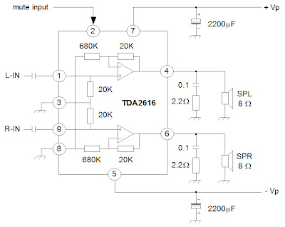 |
| Schematic TDA2616 |
Wednesday, October 16, 2013
LM3914 IC based on Simple Battery Tester
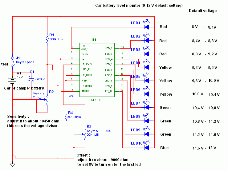 This circuit employs the popular and easy to find LM3914 IC. This kind of IC is quite very simple to drive, requires no voltage regulators (it features a built in voltage regulator) and can be powered from almost every resource.
This LM3914 IC based on Simple Battery Tester is very simple to explain:
Once the test switch is pushed, the Car battery voltage is supply into a high impedance voltage divider. His function is to divide 12V to 1, 25V (or lower values to reduced values). This solution is much better than enabling the internal voltage regulator set the 12V sample voltage to be feed into the internal voltage divider simply because it cannot regulate 12V if the voltage falls lower (linear regulators only step down). Simply wiring with no change, the regulator provides secure 1, 25V which can be fed into the precision internal resistor cascade to create sample voltages to the internal comparators.
In any case the default establishing let you to determine voltages between 8 and 12V however you can measure even from 0V to 12V setting the offset trimmer to 0 (but i believe that below 9 volt your vehicle would not start). There is a smoothing capacitor (4700uF 16V) it is used to adsorb EMF noises produced from the ignition coil if youre testing the battery during the engine working. Diesel engines would not need it, but i am not sure. If you want more a level graph rather than a bar graph simply disconnect pin 9 on the IC (MODE) from power. The calculations are usually simple (default).
Wednesday, October 9, 2013
Datasheet IC Amplifier AN7143 BA5406
This time I will post about datasheet of some IC that was applied to the power amplifier. Some of his IC from IC AN7143, AN7145L, AN7145H, AN .... , Up to BA5406. Here is the datasheet it in the form of images that you can download.
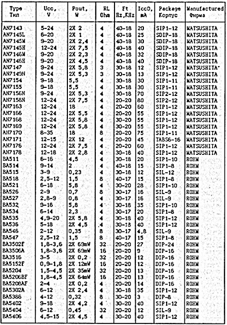 |
| Datasheet IC Amplifier AN7143 - BA5406 |
Tuesday, October 8, 2013
USB SPDIF DAC with IC PCM 2902
The tool that I made and I discuss in this article I give the name USB SPDIF DAC Every word in the name corresponds to the function of the tool that I made this.
USB, this device serves to take the music information in digital form from a computer via the USB port
SPDIF, this tool can output digital music information received through the USB port, through the SPDIF output terminal that is also present in this device, so if you have a DAC that does not have a USB input, you can still use and do not need to buy a new DAC that has an input USB.
DAC, this tool can convert the digital signals derived from the USB port, an analog signal, which you can connect to the amplifier to the ahirnya you can hear the speaker
Scheme of the USB DAC can be seen in Figure 1 below.USB, this device serves to take the music information in digital form from a computer via the USB port
SPDIF, this tool can output digital music information received through the USB port, through the SPDIF output terminal that is also present in this device, so if you have a DAC that does not have a USB input, you can still use and do not need to buy a new DAC that has an input USB.
DAC, this tool can convert the digital signals derived from the USB port, an analog signal, which you can connect to the amplifier to the ahirnya you can hear the speaker
 |
| Click to view larger. | Figure 1 |
As you can see on the schematic in Figure 1 above, which is the heart of the circuit is IC USB DAC PCM2902 made by Texas Instrument, other than that I also added a digital SPDIF output isolation transformer on from this series. 2902 PCM encoding decoding work on the principle that generally abbreviated as word CODEC.
The new circuit will work when the USB input port terminal in the circuit connected to the computer, at this voltage 5V on the USB port of any computer will be triggering the circuit to begin work, and vice versa when the computer is turned off then the circuit will be in standby mode to wait until there is more tension 5V from USB port of computer.
When the received voltage is 5V USB port the computer then the circuit will begin to receive the digital data files during the grace period of 1 ms, all data received during the period of time of 1 ms is called a frame, the data in the first frame is stored in a memory buffer that is in the PCM2902, then the circuit will start the second frame as well as long lead times for 1mS, 1mS a second after the first data from the file will be converted into analog signals for analog terminal is then removed through out the pin 15 and 16 of the PCM2902, other than that this digital signal simultaneously will also excreted through the DOUT terminal pin 25 of the PCM2902 DAC to be connected to older products that do not have a USB input terminal. In addition to functioning as a DAC, PCM2902 actually also has other functions such as setting volume level and ADC, but the circuit that I developed is only aimed for the ADC and the conversion from USB to SPDIF.
Proposed Power Supply For USB SPDIF DAC
Power Supply that I use in this project using the configuration has been proven able to tame the hum in the tube 26, the power supply has karakater very stable, low noise and low impedance, but complicated to make, so for the purposes of this project I recommend another series that is not as complicated Heater power supply 26, but the quality is still better than most of the power supply kit used in the DAC in general, Figure 2 below is the recommendation power supply for USB DAC this project.
 |
| Click to view larger. | Figure 2 |
1. Diode bridge and capacitor input filter
2. TL431 as the reference voltage
3. OP Amp OP27 as the error amplifier
4. BD139 transistor as a pass transistor This configuration is basically the general configuration of a linear regulator series, very much the regulator IC using this configuration, but the circuit in Figure 2 above has several advantages that are not owned by the regulator circuit in the form of IC a) high stability, since it uses a reference voltage source of good quality is TL431, and therefore not in a package with a pass transistor, the heat of the pass transistor can not seep into the source of reference voltage and makes it unstable, this sort of thing happens in IC voltage regulator. b) Using the Op Amp high quality, which in this case OP27, so it is not easy to oscillate as the OpAmp used in the regulator IC. c) If there is a chance you could also replace the TL431 or OP27 Op Amp voltage source and another that is expected to be better than either of these components.
 |
| Series of the finished PCB, top view |
 |
| IC PCM2902 |
Sunday, October 6, 2013
High temperature protector with IC 3584
IC 3584 has thermal protection or voltage automatically shutdown when the temperature at IC exceed 150 degrees or more. You can operate this circuit at the transistor or IC heatsing, if a transistor or IC had exceeded the limit of the heat circuit automatically shutdown.How to use a thermal shutdown circuit above that is first given a circuit of voltage V+,V-,and ground , the given a voltage Vin to be created automatically shutdown if the temperature is high , and the output is inserted in the circuit of an amplifier or other. Then IC embedded in the heatsing or case, which if too hot will shutdown alone. If the circuit already decided voltage, the voltage will re-connect if the temperature returns to normal.

Saturday, October 5, 2013
Multiplexer with TTL IC 74251
Actually you can not bother to design a multiplexer using logic gates because it has many special IC which functioned for a multiplexer.

One of the TTL ICs from the family that you can use to fulfill the function of a multiplexer is IC 74 251. At the IC there are 8 input channels and 3-bit selector and the other lane as a control reset and inverting output. As a note if you are using TTL ICs for your electronic circuit, the voltage supply that is allowed a maximum of 5 volts. So you can be more familiar with the workings of this multiplexer ic, IC74251 consider the truth table below:
C | B | A | G | Y | W |
X | X | X | 1 | Z | Z |
0 | 0 | 0 | 0 | D0 | D0’ |
0 | 0 | 1 | 0 | D1 | D1’ |
0 | 1 | 0 | 0 | D2 | D2’ |
0 | 1 | 1 | 0 | D3 | D3’ |
1 | 0 | 0 | 0 | D4 | D4’ |
1 | 0 | 1 | 0 | D5 | D5’ |
1 | 1 | 0 | 0 | D6 | D6’ |
1 | 1 | 1 | 0 | D7 | D7’ |
Z = High impedance (off) | |||||
D0,D1…D7 = Representing the output of the input lines D | |||||
Thursday, October 3, 2013
Emergency Lamp using IC 555

Emergency Lamp With 555 is one solution for lighting during power outages. With Emergency Lamp Series 555 uses a 12VDC voltage source that can be supplied from the 12V battery. Emergency Lamp 555 Series With these very simple and easy to make because all the components easily available in the market.
Emergency Lamp Series With this 555 can turn on the light 5W-10W. The circuit is built with an astable multivibrator with the IC 555 that is used to mendrive transformer through Q1. For more details can be viewed directly from the series Emergency Lamp With 555 follows.
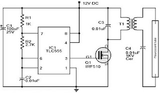 |
| Emergency Lamp Using TLC555 |
Working frequency range of 555 Emergency Lamp With this set of configurations R1, R2 and C2. T1 in series Emergency Lamp With 10V 500mA 555 is a transformer. Secondary part (0-10V) is connected to the Q1 to be given the signal from the multivibrator. Then the primary (0-220V) is connected to the lamp.
Thursday, September 26, 2013
Schematic Audio Amplifier with IC TDA2030
This schematic is great for those of you who frequent of use IC TDA2030. In addition to the simple schematic is also very clear , in modification accurate enough to make a sound that is more clear, soft , and loud. And if you interest to try this schematic.
See this circuit , datsheet ic TDA2030 and TDA 2040 , and IC TDA2030 equation below :

Datasheet IC TDA2030
Vcc = 6-18 V
Pout = 14 W
RL = 4 Ohm
Ft = 20hz - 20Khz
Icco = 40 mA
Package = TO-220
Manufactered = TELEFUNKEN
Datasheet IC TDA2040
Vcc = 3-20 V
Pout = 20 W
RL = 4 Ohm
Ft = 20hz - 20Khz
Icco = 40 mA
Package = TO-220
Manufactered = PHILIPS
Other use IC TBA 2030 or TDA2040, In this circuit you can use the following IC :
A2030
K174YH19
LM1875
TDA2006
TDA2030A
TDA2040A
MPC1238
or you can call, Equation IC TDA2030 / TDA2040
Thursday, September 19, 2013
Police Lights Circuit with 555 and 4017 IC
This circuit uses a 555 timer which is setup to both runn in an Astable operating mode. This generates a continuous output via Pin 3 in the form of a square wave. When the timers output changes to a high state this triggers the a cycle on the 4017 4017 decade counter telling it to output the next sequential output high. The outputs of the 4017 are connected to the LEDs turning them on and off.
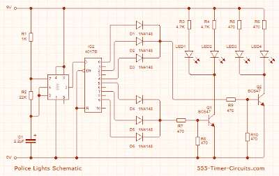 |
| Police Lights Circuit Schematic |
Thursday, September 12, 2013
120 Watt power amplifier with IC TDA2025
Minimum voltage require 12 Volts and maximum voltage require 40 Volts DC . This circuit is very simple , but output is very high . Power output 120 Watt 4 Ohm impedance. See circuit below :
 |
| TDA2025 Very high intregated Power IC |
Subscribe to:
Posts (Atom)