Showing posts with label volt. Show all posts

Wednesday, November 20, 2013

3V to 40 Volt DC Converter Circuit

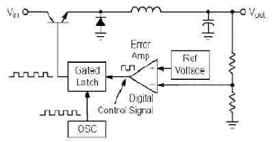
Switching regulator subsystems intended for use as dc to dc converters. 3V to 40 Volt DC Converter circuit | The use of switching regulators is becoming more pronounced over that of linear regulators because the size reductions in new equipment designs require greater conversion efficiency. Another major advantage of the switching regulator is that it has increasednapplication flexibility of output voltage. The output can be less than, greater than, or of opposite polarity to that of the input voltage.

3V to 40 Volt DC Converter Circuit

Switching regulator subsystems intended for use as dc to dc converters. 3V to 40 Volt DC Converter circuit

The MC34063 series is a monolithic control circuit containing all the active functions required for dc to dc converters. This device contains an internal temperature compensated reference, comparator, controlled duty cycle oscillator with an active peak current limit circuit, driver, and a high current output switch. This series was specifically designed to be incorporated in step–up, step–down and voltage–inverting converter applications. These functions are contained in an 8–pin dual in–line package.

FEATURES 3V to 40 Volt DC Converter :
· Wide Input Voltage Range 3 V to 40 V
· Precision Internal Reference 2%
· High Output Switch Current Up to 1.5 A
· Short-Circuit Current Limiting
· Adjustable Output Voltage
· Low Standby Current
· Oscillator Frequency Up to 100 kHz
[Continue Reading]

Tuesday, November 12, 2013

15 Volt output regulated power supply circuit

The circuit above get from -20 volt DC the rectifier diode which is fed to the collector of the Darling pn pass transistor , a TIP105 . The diode use IN4007. The base drive to the TIP105 is supplied through resistor R5. The base of the TIP105 is driven from Vz terminal at pin 9 , which is the anode of a 6.2 -V zener diode that connects to the emitter of the uA723 output control transistor.
The method of providing the positive feedback required for foldback action is shown. This technique introduces positive feedback by increased current flow through resistor R1 and R2 under short circuit conditions. This forward biases the base emitter junction of the 2N2907 sensing transistor , which reduces base drive to the TIP105.
[Continue Reading]

Tuesday, November 5, 2013

3 Volt Car Adapter

The The Schematic of 3 volt Car Adapter was posted by taking part in type Car. Please examine suspiciously and realize on schematic design pictures of The Schematic of 3 volt Car Adapter to find specify in order.

3 volt Car Adapter Schematics
This 3 volts Car Device journey is based on a provide LT1074CT switching control IC. The schematic shows the LT1074CT misused equally a affirmatory step-down before ‘buck’ convertor. The ’switcher’ is old to trade a +12-volt car barrage emf consume to +3 volts pro make use of with the personalised goodbye-fi’s and handheld games for the author’s two boisterous children on sesquipedalian car journeys. State on under ten time of age, children offer rarely remain see you later-fi admirer’s and are mostly not caring with at all disturbance generated by the ’switcher ‘circuit.

The journeying is coupled to the car +12-vs. order via the smoke lighter socket - is rational to use a compound edition of the fag light stopple. The +12-against arrives on the relations via screw- pole impede J2. Diode D2 provides a verso emf indorsement, scrap C3 decouples the input to the switcher IC.

[Continue Reading]

Tuesday, October 15, 2013

POWER SUPPLAY 13 8 Volt Schematic

POWER SUPPLAY 13,8 Volt Schematic

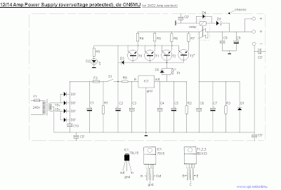
Part list for 12 Amp BDX33-based power supply:

  • 2 x 15 volt 6+ amps

  • 2 times two MR750 (MR7510) diodes (MR750 = 6 Ampere diode) or 2 times 3 1N5401 (1N5408) diodes.

  • F1 = 1 Amp

  • F2 = 15 amp

  • R1 2k2 1 Watt

  • R2 10k

  • R3 1k 0.5 watt

  • R4,R5,R6,R7 0.1 ohm 10 watt

  • R8 4.7

  • R9 6k8

  • C1 two times 4700uF/35v

  • C2 330uF/35v

  • C0,C3,C4,C6,C10 100nF

  • C7 330uF/25v

  • C8 47nF

  • C9 47uF/25v

  • D1 1N5401

  • D2 LED

  • D3, D4, D5 1N4001

  • IC1 78L15

  • relay 12 volt 2x5 amp switching

  • 3 darlington transistors: T0,T1,T2 = BDX-33 NPN TO-220 transistor

  • Zd 8 or 9 volt, 5 watt

  • P1 2k trimmer

If using a bridge rectifier (like in schematic 2) you do not need 2 x 15 volts 6 amps, but 1 x 15 volt 10+ Amps

Part list for 20 Amp BDX33-based power supply:

  • 2 x 15 volt 12+ amps

  • 2 times 3 MR750 (MR7510) diodes (MR750 = 6 Ampere diode) or 2 times 5 1N5401 (1N5408) diodes.

  • F1 = 2 Amp

  • F2 = 25 amp

  • R1 2k2 1 Watt

  • R2 10k

  • R3 1k 0.5 watt

  • R4,R5,R6,R7 0.1 ohm 10 watt

  • R8 4.7

  • R9 6k8

  • C1 22000uF/35v

  • C2 330uF/35v

  • C0,C3,C4,C6,C10 100nF

  • C7 330uF/25v

  • C8 47nF

  • C9 47uF/25v

  • D1 1N5401

  • D2 LED

  • D3, D4, D5 1N4001

  • IC1 7815

  • relay 12 volt 10 amp switching

  • Four darlington transistors: T0,T1,T2,T3 = BDX-33 NPN TO-220 transistor

  • Zd 8 or 9 volt, 5 watt

  • P1 2k trimmer

If using a bridge rectifier (like in schematic 2) you do not need 2 x 15 volts 12 amps, but 1 x 15 volt 20 Amps

[Continue Reading]

Monday, October 7, 2013

6 12 Volt audio amplifier circuits
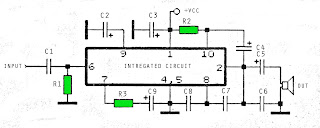
6 - 12 Volt amplifier circuit
The above is an amplifier circuit using supply voltages from 6 volts DC to 12 Volt DC. Power output of the amplifier is quite low with only 1 Watt 8 ohm impedance. You can apply this to the audio signal amplifiers that require strengthening are not so large as in the pocket radio.
Part List :
R1 =  100K
R2 = 39R
R3 = 100R
C1 = 100nF
C2 = 100uF
C3 = 100uF
C4 = 100uF
C5 = 470uF
C6 = 100nF
C7 = 68pF
C8 = 1nF
C9 = 47uF
IC = SFC2790C
[Continue Reading]

Tuesday, October 1, 2013

6 to 12 Volt Power Supply Inverter
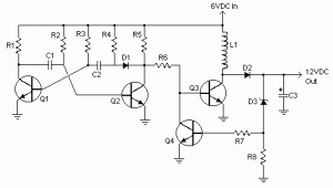
This inverter circuit can provide up to 800mA of 12V power from a 6V supply. For example, you could run 12V car accessories in a 6V (British?) car. The circuit is simple, about 75% efficient and quite useful. By changing just a few components, you can also modify it for different voltages.


6 to 12 Volt Power Supply Inverter


Part List:

R1, R4 2.2K 1/4W Resistor

R2, R3 4.7K 1/4W Resistor

R5 1K 1/4W Resistor

R6 1.5K 1/4W Resistor

R7 33K 1/4W Resistor

R8 10K 1/4W Resistor

C1,C2 0.1uF Ceramic Disc Capacitor

C3 470uF 25V Electrolytic Capcitor

D1 1N914 Diode

D2 1N4004 Diode

D3 12V 400mW Zener Diode

Q1, Q2, Q4 BC547 NPN Transistor

Q3 BD679 NPN Transistor

L1 See Notes

MISC Heatsink For Q3, Binding Posts (For Input/Output), Wire, Board

source:LINK
[Continue Reading]

Friday, September 20, 2013

9 Volt Audio Power Amplifier

This is an audio amplifier to facilitate can be there used with a miniature 9 volt Battery Operated,Current draw on since insufficiently as 5 milliamps.And amplification up to 500 mW. Which is sufficient to spread out the sound from a sound almost or else the recording stroll guy vetoed to the minor speakers evidently.

9 Volt Audio Power Amplifier Circuit
9 Volt Audio Power Amplifier
Once entering the power supply 9-volt circuit IC1 total LM386 amplifier IC size is 300-800 mW, Depending on the power supply circuit with,This is from 4-15 volts. once upon a time entered into the input pin 3,The non inverting pin to amplifier non-return time.C1 resolve occur served remove out the clatter input to ground.And C2 increases the rate of amplifier,C2 is to add supplementary help.But if the C2 Too much distortion (the C2 must not exceed 100uF).The output of IC1 is out cold of the pin 5 through C4 coupling audio signals to better and DC blockade and not voted for to the spokesperson.on behalf of the audio portion bidding besides befall fed back through R2 and C3 to the above what is usual frequency response better.

[Continue Reading]

Saturday, September 14, 2013

15 Volt Stabilizer circuit

15 volt stabilizer schematicIn this time I will share about the circuit voltage stablizer or stabilization using IC 7815 and 7915, with a minimum of 17.5V to 50V input. The output of this circuit will issue with the current 15V voltage in accordance with the input. Stabilizer is also equipped with reinforcement by transistor 2N3055 and MJ2955.


15V stabilizer schematic
15-volt stabilizer schematics
Part List :
D1 - D4 use 3A diode
C1 - C2 use Capacitor Elco with capacity 4700uF - 10000uF 80V
C3 - C6 use Capacitor Elco with capacity 470uF - 2200uF 50V
Q1 2N3055
Q2 MJ2955
IC 7815 and 7915

[Continue Reading]

15 Volt Stabilizer circuit

15 volt stabilizer schematicIn this time I will share about the circuit voltage stablizer or stabilization using IC 7815 and 7915, with a minimum of 17.5V to 50V input. The output of this circuit will issue with the current 15V voltage in accordance with the input. Stabilizer is also equipped with reinforcement by transistor 2N3055 and MJ2955.


15V stabilizer schematic
15-volt stabilizer schematics
Part List :
D1 - D4 use 3A diode
C1 - C2 use Capacitor Elco with capacity 4700uF - 10000uF 80V
C3 - C6 use Capacitor Elco with capacity 470uF - 2200uF 50V
Q1 2N3055
Q2 MJ2955
IC 7815 and 7915

[Continue Reading]