Showing posts with label motor. Show all posts
Showing posts with label motor. Show all posts
Wednesday, November 13, 2013
Bidirectional Motor Control Using L293 Driver
Using the L293 quadruple high-current half-H driver integrated circuit can be designed a very simple high efficiency motor control. The L293 is designed to provide bidirectional drive currents of up to 1 A at voltages from 4.5 V to 36 V. The L293D is designed to provide bidirectional drive currents of up to 600-mA at voltages from 4.5 V to 36 V.
Bidirectional Motor Control Circuit Diagram

Each output is a complete totem-pole drive circuit, with a Darlington transistor sink and a pseudo-Darlington source. Drivers are enabled in pairs, with drivers 1 and 2 enabled by 1,2EN and drivers 3 and 4 enabled by 3,4EN. When an enable input is high, the associated drivers are enabled and their outputs are active and in phase with their inputs. When the enable input is low, those drivers are disabled and their outputs are off and in the high-impedance state. With the proper data inputs, each pair of drivers forms a full-H (or bridge) reversible drive suitable for solenoid or motor applications.
External high-speed output clamp diodes should be used for inductive transient suppression. In this bidirectional stepper motor controller electronic project VCC1 is logic supply and must me between 4.5 and 7 volts ( typically 5 volt) and VCC2 is the power supply for the motor and must be from VCC1 up to 36 volts.
Bidirectional Motor Control Circuit Diagram
Each output is a complete totem-pole drive circuit, with a Darlington transistor sink and a pseudo-Darlington source. Drivers are enabled in pairs, with drivers 1 and 2 enabled by 1,2EN and drivers 3 and 4 enabled by 3,4EN. When an enable input is high, the associated drivers are enabled and their outputs are active and in phase with their inputs. When the enable input is low, those drivers are disabled and their outputs are off and in the high-impedance state. With the proper data inputs, each pair of drivers forms a full-H (or bridge) reversible drive suitable for solenoid or motor applications.
External high-speed output clamp diodes should be used for inductive transient suppression. In this bidirectional stepper motor controller electronic project VCC1 is logic supply and must me between 4.5 and 7 volts ( typically 5 volt) and VCC2 is the power supply for the motor and must be from VCC1 up to 36 volts.

Saturday, October 26, 2013
Stepper Motor Controller Using by A3952S
Using the A3952S stepper motor controller ( designed by Allegro MicroSystems ) we can design a very simple and useful motor driver circuit that can be used in many electronic applications . A3952S stepper motor controller is capable of continuous output currents up to 2 A and operating voltages range up to 50 V. Internal fixed off-time PWM current-control circuitry can be used to regulate the maximum load current to a desired value. The MODE terminal can be used to optimize the performance of the device in microstepping / sinusoidal stepper motor drive applications.
A3952S Stepper Motor Controller Circuit diagram

When the average load current is increasing, slow-decay mode is used to limit the switching losses in the device and iron losses in the motor. The thermal performance in applications with high load currents and/or high duty cycles can be improved by adding external diodes in parallel with the internal diodes. In internal PWM slow-decay applications, only the two top-side (flyback) diodes need be added. For internal fast-decay PWM, or external PHASE or ENABLE input PWM applications, all four external diodes should be added for maximum junction temperature reduction .
As you can see in the schematic diagram , this stepper motor driver circuit require two A3952S circuits and other few additional electronic components.
A3952S Stepper Motor Controller Circuit diagram
As you can see in the schematic diagram , this stepper motor driver circuit require two A3952S circuits and other few additional electronic components.
Thursday, October 17, 2013
Motor driver L298 Circuit
DC motor driver with H-Bridge IC L293D
IC H Bridge DC motor driver L298 has two H-Bridge circuit in it, so it can be used to download the drive two DC motors. H Bridge DC motor driver L298 each can deliver currents up to 2A. However, in use, the H Bridge DC motor driver L298 can be used in parallel, so the ability to deliver the H Bridge DC motor driver L298 flow into 4A. The consequences of the installation of H Bridge L298 DC motor driver with the parallel mode, you need 2 pieces Bridge H L298 DC motor driver to control two DC motors using H bridge DC motor driver L298 in parallel mode.
H Bridge Pin IC L298 DC motor driver which is connected in parallel operation mode:* OUT1 connected to OUT4.
* OUT2 OUT3 linked.
* IN1 is connected to IN4.
* IN2 connected to IN3.
* ENABLE ENABLE A linked to B.

OUT1/OUT4 and OUT2/OUT3 associated with DC motors to be controlled.
Please note that the output of the L298 does not have a safety diode. Thus, the need to add two diodes - flyback diodes, with appropriate current capability, at any point output.
Friday, September 13, 2013
DC Motor Speed Control using PWM
 DC Motor Speed Control using PWM
 Usually to make a simple PWM (for practice or the introduction PWM) fans to use some of the facts of the op-amp circuit, which consists of Schmitt Trigger circuit, the integrator and comparator.
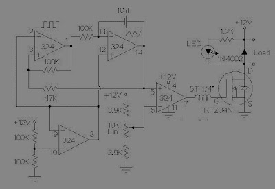
Schmitt Trigger function that produces a square wave will become the sawtooth wave or integrator is also called common rail and the ramp compared to a reference voltage that can change a lot of stress. So the result is a PWM output.
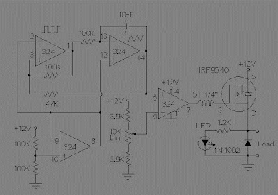
These two schemes are variations of different circuit PWM. The diagrams are for 12V operation and there are upper (ground) and low side (+12 V common) versions. The version of the lower circuit uses an N-channel FET, the high-side version of the circuit uses a P-channel FET. N channel devices tend to handle more current P-channel devices, which are also less expensive. The version of the high side of the circuit is useful when a portion of the load must be grounded.
This circuit can change a fairly high amount of current, a MOSFET IRFZ34N can handle over 35 Amps if connected to an adequate heat sink. Higher power FETs, such as IRF1010Z IRFZ48N or can be substituted if even larger currents are required. It is also possible to connect multiple FETs in parallel even more current capacity. Always use thermally conductive grease between the FET and the heat sink, and remember that the heatsink is under stress.
Inductive loads (motors) may require special care because it can generate large voltage spikes that can damage the MOSFET. Replacing a 1N4002 fast recovery diode can help absorb the recoil reverse voltage when driving an inductive load like a motor. If you use these circuits to experiment with electric vehicles, be sure to install a circuit breaker in series with the battery, the switch should be easy to reach by the driver. This is especially important given the fact that when non-MOSFETs, is often cut, leaving the engine running at full speed
Subscribe to:
Posts (Atom)