Showing posts with label sensor. Show all posts
Showing posts with label sensor. Show all posts
Monday, November 18, 2013
Fire Sensor Hamamatsu UVTRON
Fire Sensor (Hamamatsu UVTRON)

[Continue Reading]
UVTRON Hamamatsu R2868 is a sensor that detects a flame fire that emit ultraviolet light. Ultraviolet light emitted from a candle flame is a 5 meter can be detected by this sensor. This sensor can also detect some unseen phenomena such as high voltage transmission.
In order for this UVTRON sensors to connect to the system microcontroller then required a series of lawyer-signal condition that serves to change the response of UVTRON into pulses that can be recognized by the system microcontroller. With Module C3704 UVTRON response will then be processed into about 10 pulses mS and the maximum current 100mA. The output module uses the open configuration collector.

Saturday, November 9, 2013
Accelerometer Sensor

Sensor Output Accelerometer MMA 3201 is still in the form of analog data so that the need for an ADC to process the data. Data released by Sensor Accelerometer MMA 3201 is a linear form of X and Y axis, the second determines the acceleration motion data payload.
 |
| Accelerator sensor with MMA 3201 |
Feature Sensor Accelerometer MMA 3201
- Sensitivity in two separate axes: 40g X-axis and 40g Y-axis
- Integral Signal Conditioning
- Linear Output
- Ratiometric Performance
- 4th Order Bessel Filter Preserves Pulse Shape Integrity
- Calibrated Self-test
- Low Voltage Detect, Clock Monitor, and EPROM Parity Check status
- Transducer Hermetically Sealed at Wafer Level for Superior Reliability
- Robust Design, High Shocks Survivability
Thursday, October 31, 2013
Line Following Robot Sensor
This Line Following Robot sensor or surface scanner for robots is a very simple, stamp-sized, short range (5-10mm) Infrared proximity detector wired around a standard reflective opto-sensor CNY70(IC1). In some disciplines, a line following robot or an electronic toy vehicle go along a predrawn black line on a white surface. In such devices, a surface scanner, pointed at the surface is used to align the right track.
IC1 contains an infrared LED and a phototransistor. The LED emit invisible infrared light on the track and the phototransistor works as a receiver. Usually, black colored surface reflects less light than white surface and more current will flow through the phototransistor when it is above a white surface. When a reflection is detected (IR light falls on the phototransistor) a current flows through R2 to ground which generates a voltage drop at the base of T1 to make it conduct. As a result, transistor T2 start conducting and the visual indicator LED(D1) lights up. Capacitor C2 works as a mini buffer.
Line Follower Robot Scanner Circuit diagram:
 After construction and installation, the scanner needs to be calibrated. Initially set P1 to its mechanical centre position and place the robot above the white portion of the track. Now slowly turn P1 to get a good response from D1. After this, fine tune P1 to reduce false detection caused by external light sources. Also ensure that the LED remains in off condition when the sensor module is on the blackarea. Repeat the process until the correct calibration is achieved.
The red color LED (D1) is only a visual indicator. You can add a suitable (5V) reed relay in parallel with D1-R4 wiring after suitable alterations to brake/stop/redirect the robot. Similarly, the High to low (H-L) transition at the collector of T2 can be used as a signal to control the logic blocks of the robot. Resistor R1 determines the operating current of the IRLED inside IC1. The sensing ability largely depends on the reflective properties of the markings on the track and the strength of the light output from IC1.
IC1 contains an infrared LED and a phototransistor. The LED emit invisible infrared light on the track and the phototransistor works as a receiver. Usually, black colored surface reflects less light than white surface and more current will flow through the phototransistor when it is above a white surface. When a reflection is detected (IR light falls on the phototransistor) a current flows through R2 to ground which generates a voltage drop at the base of T1 to make it conduct. As a result, transistor T2 start conducting and the visual indicator LED(D1) lights up. Capacitor C2 works as a mini buffer.
Line Follower Robot Scanner Circuit diagram:
The red color LED (D1) is only a visual indicator. You can add a suitable (5V) reed relay in parallel with D1-R4 wiring after suitable alterations to brake/stop/redirect the robot. Similarly, the High to low (H-L) transition at the collector of T2 can be used as a signal to control the logic blocks of the robot. Resistor R1 determines the operating current of the IRLED inside IC1. The sensing ability largely depends on the reflective properties of the markings on the track and the strength of the light output from IC1.
Sunday, October 27, 2013
Direction Sensor CMPS03

CMPS03 Compass Module Overview
Compass is a tool for navigation for a direction, a direction in this article referred to is the magnetic module CMPS03 Compas. Magnetic Compass Module CMPS03 often used in making robots in the contest.
Magnetic Compass Module Functions in the contest CMPS03 usually to provide a reference where the robots are in position and lead anywhere, then the position and direction provided by the Magnetic Compass Module reference sebgai CMPS03 the next robot motion. Magnetic Compass Module uses I2C data communication lines to mirokontroler. With adalanya I2C data communication lines from this CMPS03 this module can be connected directly to a microcontroller that suport with I2C data communication channels such as AVR ATMega. Magnetic Compass Module CMPS03 require 5 V voltage with 15mA current.
Magnetic Compass Module Functions in the contest CMPS03 usually to provide a reference where the robots are in position and lead anywhere, then the position and direction provided by the Magnetic Compass Module reference sebgai CMPS03 the next robot motion. Magnetic Compass Module uses I2C data communication lines to mirokontroler. With adalanya I2C data communication lines from this CMPS03 this module can be connected directly to a microcontroller that suport with I2C data communication channels such as AVR ATMega. Magnetic Compass Module CMPS03 require 5 V voltage with 15mA current.
 |
| CMPS03 Circuit Diagram |
Because the module using I2C Magnetic Compass CMPS03 we can use 5 lines are:
VCC + 5 V on pin 1
SCL with Pull Up resistor 10 K
SDA with Pull Up resistor 10 K
Calibrate the PIN associated with micro switch 6
Ground on PIN9
Friday, October 18, 2013
10 Channels Sensor Switch
A touch sensor switch circuit that works with 10 channels can be designed using electronic scheme in the figure below. If one of the 10 sensors is touched, the corresponding output goes in a logical state 1, the other inputs are in logic state 0.
10 Channels Sensor Switch Circuit Diagram

This 10 channel sensor switch is built using 4017 CMOS decimal counter which provides "decoded" signals. A second oscillator realized with CMOS logic gates produces clock signal. The counter is working until it achieved the desired position of the switch.
The switch can be supplied with a DC voltage between 3 and 15 volts DC.
10 Channels Sensor Switch Circuit Diagram
The switch can be supplied with a DC voltage between 3 and 15 volts DC.
Tuesday, October 15, 2013
Fire Alarm using NE555 and temperature sensor

This is a simple series of fire alarms. In this series used NE555 timer and temperature sensor to detect high temperatures. The working principle of this temperature sensor that is when the temperature is high around the sensor then there is resistance on the sensor to be small.
However if the low temperature then the resistance will be high. If the resistance of small sensors, the voltage supply will be able to flow past the sensor and activate the transistor.

IC1 NE555 as a regulator of the audio frequency. Transistors 1 and 2 are used as a driver IC1. Output (pin 3) of IC1 would trigger a transistor base T3 (SL100), which drives the speaker to produce sound the alarm. Frequency NE555 depending on resistance values of R5 and R6 and the capacitance sensor C2 temperature. When the temperature gets hot, would provide a low resistance so that supply voltage can flow into the base of transistor T1 through a diode D1 and R2.
Capacitor C1 will charge a positive voltage so that it will increase the time when the fire alarm. The greater the value of C1, the greater the positive bias applied to the base of transistor T1 (BC548). T1 collector coupled to the base transistor T2, transistor T2 provides a positive voltage to pin 4 (reset) from IC1 (NE555). Resistors R4 will make IC1 NE555 continued to be active despite no positive voltage flowing.
Monday, October 14, 2013
Electronic Component Temperature Sensor
Electronic Component Temperature Sensor
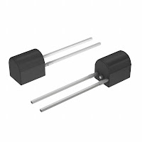 |
| Electronic Component Temperature Sensor |
Electronic components that are used for temperature sensors, among others: NTC, PTC, Thermostat, IC LM35 temperature sensor, temperature sensor IC LM335 etc. To create a series of simple electronics of the temperature sensor of the basic components of the temperature sensor, the component needs to connect to the transistors or Op-Amp as driving to the end of the circuit.
Wednesday, October 2, 2013
Line Follower Robot Sensor Concept
Line Follower Robot Sensor Concept - Sensor line detector is used in line follower robot is usually based on the principle of light reflectionto distinguish the line with the background color. In the dark color of the light absorption is greater than that of white light reflected to the sensor becomes smaller.
Position sensor to track the trajectory and the example circuit.
 |
| Line Follower Robot Sensor Concept |
Light used for the introduction of the line is usually visible light and infra-red. Sensors for visible light are commonly used are LDR (Light Depending Resistance), while for the infrared light is atransistor and photo diode (photodiode). Sensors placed at the bottom of the frame to hang the robot, so that its position can be located just above the track to be read.
Subscribe to:
Posts (Atom)