Showing posts with label supply. Show all posts
Showing posts with label supply. Show all posts
Sunday, December 15, 2013
0 300V Variable High Voltage Power Supply
Here is the variable high voltage dc power supply circuit, which we can customize the output voltage from 0 to 311Vdc, and it is protected the current over limit that we define at about 100 mA.

In the circuit you can see the T1 is a mains transformer with a ratio of 1:1, for security reasons , and reduces noise signal as well. Then the mains voltage from the T1 is rectified to DCvolt with bridge diode D1-D4, We use a No. 1N4007 that withstand voltage as 1,000V at the current 1A and and this DCV is filtered through the capacitor C1 – 220uF 400V be the big size electrolytic types, by the voltage drop across C1 is about 311VDC.
The power MOSFET Q1 is controlled the current output, with using the resistor R3 – 500K adjust the voltage gate pin of Q1. The ZENER diode ZD1-12V is available prevent over voltage at gate pin of the Q2 if we not has it when high volt the Q2 may be damaged.
The transistor Q2-BC337 and the shunt resistor R2 – 3.3ohm are added for as a current limiter. When the current output is too increased, the Q2 will stop the gate pin of the Q1 immediately, which will be guard the higher current output. The degree of R3 gets from testing in this circuit, which depending on the gain of the transistor or the hFE value, so you may need to tune the value of R2

Friday, November 22, 2013
Power supply with driver TEA1507
Power supply with driver TEA1507 is mostly used by TV branded PHILIPS. Power Supply has an efficiency rate of up to 90% - thus requiring less cooling, as well as stand-by power required is less than 1 watt.
Power Supply with TEA driver is equipped with a variety of surge protector that has a high reliability - not easily damaged if any part of a damaged power supply circuit and power transistor or FET heat is not easily damaged. Power supply circuits are dapatapat working on ac input voltage between 85 up to 275v. The way it works with the driver circuit power supply TEA 1507 is quite simple, so easy tracking of damage to the circuit.

The picture above is the basic power supply circuit with TEA1507
Saturday, November 16, 2013
Tips for caring power supply units
 Power Supply on a computer is an energy source that drives the computer you. With power supply, hardware on the computer is given "power" to can work in accordance with their respective functions Power Supply on a computer to work as a flow modifier (Adapter) from AC current into DC.
 Power supply is working on 2 pieces of 5-volt DC voltage and 12 Volt. In a power supply, voltage 12 volt is usually characterized with a yellow cable, while the voltage is 5 Volt is marked with cable red.

Tips to maintain power supply in order to remain durable
1. Make sure you buy the power supply to suit your computer needs. Buy power supply that is guaranteed quality.
2. Make sure when you install a power supply on your computer already in the correct position. Make a tightening of the socket-outlet power supply to the motherboard, hard drive, CDRom, etc.. If you do the installation is not correct it will be fatal and can be a fire or a short-circuit will occur on your hardware.
3. Check your power supply voltages in the BIOS Hardware Monitor or Hardware Management. Is it permissible range qualified. If it does not fit will usually be marked with red writing.
4. Check the condition of the fan at any time at least 3 months. Or, when you have a problem on your computer such as Hang, Restart and Total death. Clean the fan if necessary and give a lubricant (contact cleaner) in as a fan.
5. Do not put your CPU is too close (mepet) with the wall. Because it would cause air circulation fan should be running with the operation will be disrupted.
1. Make sure you buy the power supply to suit your computer needs. Buy power supply that is guaranteed quality.
2. Make sure when you install a power supply on your computer already in the correct position. Make a tightening of the socket-outlet power supply to the motherboard, hard drive, CDRom, etc.. If you do the installation is not correct it will be fatal and can be a fire or a short-circuit will occur on your hardware.
3. Check your power supply voltages in the BIOS Hardware Monitor or Hardware Management. Is it permissible range qualified. If it does not fit will usually be marked with red writing.
4. Check the condition of the fan at any time at least 3 months. Or, when you have a problem on your computer such as Hang, Restart and Total death. Clean the fan if necessary and give a lubricant (contact cleaner) in as a fan.
5. Do not put your CPU is too close (mepet) with the wall. Because it would cause air circulation fan should be running with the operation will be disrupted.
Tuesday, November 12, 2013
Troubleshooting STR IC Regulator Power Supply
A. Unable to start.
Can be caused by:
- No start-up voltage supply Vcc or a voltage less than 16V
- Electrolityc Capacitors supply voltage Vcc filter dry.
2. Led indicator blinking
If the supply voltage Vcc examined rocking. This is because the regulator of life and death because OVLO work., Die-protectionist regulators and auto start life over and over. If it is turned off Electrolityc Capacitors usually still keep the rest of the cargo.
Can be caused by:
- Electrolityc Capacitors supply voltage Vcc filter on a pin-4 dry. Replace with a value equal to or slightly larger. - triger UVLO
- input filter capacitor on pin-1 feed dry behind the declining value - triger OLP
- Rectifier diode of the switching transformer is damaged (sometimes when examined with avo-meter looks like a still good)
- cause the supply voltage Vcc drops of the switching transformer (UVLO)
- Part damage or broken lines on the feedback circuit of the voltage regulator through B to photocoupler - triger OVP
- Electrolityc Capacitors dry filter voltage B - triger OVP
- One of the output voltage of the switching transformer secondaries there is a short (over load) - triger OLP
- Soft start capacitor value decreases - triger OLP

3. Noise arising (noise)
Can be caused by:
- Transformer windings slack.
- If there are ceramic capacitors - can sometimes cause interference noise due to its characteristic piezoelectrik like crystal resonator. Replace with film capacitors.
4. When the st-by normal stress. But when the power is on the regulator directly off protectionism no voltage on the secondary this part. Electrolityc Capacitors are still storing charge.
Can be caused by:
- Sensor OVP small value resistor on pin-2 to the ground so that the value of delayed triger to OLP or OCP.
- Regulator IC is damaged
---------------------------------------------------------------------------------------------------------------------------
Note: Be careful when the regulator is not working. Because of Electrolityc Capacitors may still have a charge when turned off.
15 Volt output regulated power supply circuit

The circuit above get from -20 volt DC the rectifier diode which is fed to the collector of the Darling pn pass transistor , a TIP105 . The diode use IN4007. The base drive to the TIP105 is supplied through resistor R5. The base of the TIP105 is driven from Vz terminal at pin 9 , which is the anode of a 6.2 -V zener diode that connects to the emitter of the uA723 output control transistor.The method of providing the positive feedback required for foldback action is shown. This technique introduces positive feedback by increased current flow through resistor R1 and R2 under short circuit conditions. This forward biases the base emitter junction of the 2N2907 sensing transistor , which reduces base drive to the TIP105.
Friday, November 1, 2013
1 3V DC to 12 2V DC Regulator Power Supply
Power supply circuit to generate output below were variations between 1.3V DC to 12.2V DC with 1A current.
In addition, the power supply circuit is also equipped with over-current protection or shield against belebih flow. Power supply circuit is very simple, but the quality is quite good, made her basiskan regulator IC LM723 is a pretty legendary.
In addition, the power supply circuit is also equipped with over-current protection or shield against belebih flow. Power supply circuit is very simple, but the quality is quite good, made her basiskan regulator IC LM723 is a pretty legendary.

Description:
R2 to set the output voltage. The maximum current is determined by R3, over-current protection circuit inside the LM723 to detect the voltage on R3, if it reaches 0.65 V, the voltage output will be off her. So the current through R3 can not exceed 0.65 / R3 although output short-circuit in his.
C3 and C4 are ceramic capacitors, as much as possible directly soldered to the PCB, this is because the LM723 is prone to oscillation that is not cool.
LM723 works with 9.5V input voltage to 40 V DC and the LM723 can generate its own current of 150mA when the output voltage is not more than 6-7V under input voltage.
Specifications:
Output (value estimated):
Vmin = (R4 + R5) / (R5 * 1.3)
Vmax = (7.15 / R5) * (R4 + R5)
Imax = 0.65/R3
Max. Power on R3: 0.42/R3
Min. DC Input Voltage (pin 12 to pin 7): Vmax + 5
Component List:
B1 40V/2.5A
C1 2200uF (3300uF even better)
C2 4.7uF
C3 100nF
C4 1NF
C5 330nF
C6 100uF
Green LED D1
D2 1N4003
F1 0.2A F
F2 2A M
IC1 LM723 (in a DIL14 plastic package)
R1 1k
R2 Pot. 5k
R3 0.56R/2W
R4 3.3k
R5 4.7k
S1 250V/1A
T1 2N3055 on a heatsink 5K / W
TR1 220V/17V/1.5
source [link]
Friday, October 11, 2013
LM338 Adjustable power supply circuit
Its a circuit of adjustable 10-A regulator , with the IC LM338. The first working mode 220V AC current reveled by T1 to 30VAC then rectified by four diodes D1,D2,D3,and D4 and become less than 30VDC. Not enough to be rectified voltage is filtered in the C1 and C2. And CT/ground should not be used because the voltage needed on the circuit above is only plus and min, so the ground was stopped first. After the voltage is filtered and then go to two IC , for setting the voltage output is on Vr1, the output voltage of 0 to 30 Volt DC regulated.
Part List :
R1 = 240R
R2 = 720R
R3 = 120R
Vr1 = 1K trim
D1-D4 = 1N4007
C1 = 6800uF/50V
C2 = 6800uF/50V
C3 = 0,1uF/50V
C4 = 1uF/50V
IC1,2 = LM338
T1 = Stepdown transformer 220V to 30V 10A

Tuesday, October 1, 2013
6 to 12 Volt Power Supply Inverter
This inverter circuit can provide up to 800mA of 12V power from a 6V supply. For example, you could run 12V car accessories in a 6V (British?) car. The circuit is simple, about 75% efficient and quite useful. By changing just a few components, you can also modify it for different voltages.
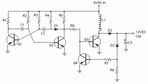
Part List:
R1, R4 2.2K 1/4W Resistor
R2, R3 4.7K 1/4W Resistor
R5 1K 1/4W Resistor
R6 1.5K 1/4W Resistor
R7 33K 1/4W Resistor
R8 10K 1/4W Resistor
C1,C2 0.1uF Ceramic Disc Capacitor
C3 470uF 25V Electrolytic Capcitor
D1 1N914 Diode
D2 1N4004 Diode
D3 12V 400mW Zener Diode
Q1, Q2, Q4 BC547 NPN Transistor
Q3 BD679 NPN Transistor
L1 See Notes
MISC Heatsink For Q3, Binding Posts (For Input/Output), Wire, Board
[Continue Reading]
Part List:
R1, R4 2.2K 1/4W Resistor
R2, R3 4.7K 1/4W Resistor
R5 1K 1/4W Resistor
R6 1.5K 1/4W Resistor
R7 33K 1/4W Resistor
R8 10K 1/4W Resistor
C1,C2 0.1uF Ceramic Disc Capacitor
C3 470uF 25V Electrolytic Capcitor
D1 1N914 Diode
D2 1N4004 Diode
D3 12V 400mW Zener Diode
Q1, Q2, Q4 BC547 NPN Transistor
Q3 BD679 NPN Transistor
L1 See Notes
MISC Heatsink For Q3, Binding Posts (For Input/Output), Wire, Board
source:LINK
Thursday, September 19, 2013
Switching Mode Power Supply using STR
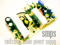 Switching Power supply circuit produces a voltage B + (dc voltage) needed television series taken from the net voltage household. G7 G7A chassis and power supply circuit using cool / cold in which the primary and the secondary power supply electrically separated so that the chassis can be directly connected to another device via an audio video terminal.
 |
| Switching power supply |
This power supply circuit is a type SMPS (Switching Mode Power Supply) using mosfet transistor integrated circuit voltage controller in one IC package, namely STR-W6654. This IC will control the duty cycle of time off Vth2 Mosfet transistor to control the output voltage. Besides, the IC is also equipped with a safety circuit against overvoltage (OVP), overcurrent (OCP) and over temperature (TSD) circuit is working on 220V ac voltage with the input ac voltage range of 176V to 260V ac or known by the Wide range Regulators.
How to Work Series
Initial bias voltage dc pin6 IC801 obtained from an ac voltage through D811 and R817, in the beginning of this pin6 high input impedance, or simply need a current of about 100uA, if the voltage has reached the 10V, the IC will mendrive Mosfet transistor into On and transformer will generate stress induction through V1 , R819 and D816 making this pin6 voltage rises to 16V working voltage, and at this point impedance pin6 will shrink or current will increase to 30mA.
Voltage Stabilizer
Stabilizing the output voltage of the circuit is done by regulating the length of time off of the transistor current MOSFETs by using the feedback coupler photo released by the D807. And the D807 is controlled by the IC regulator IC802, IC is working based on the transformer secondary winding S2 (main output). Change IC802 PIN1 perceived stress will be informed on the photo coupler D807 and forwarded to the IC801 for correction.
Safety Over Voltage
In the event of errors / defects in the feedback path, the output voltage will rise out of control, but the series / IC801 has been equipped with a safety overvoltage, where pin6 IC801 can serve as a detection voltage, output voltage rises when the voltage V1 uncontrolled transformer also rises and via the R819, D816 IC801 pin voltage also rose, When the voltage reaches 34V in IC801 oscillator will stop / off switch and voltage pin6 will go down, and when the voltage reaches 7.5 V IC is going back to work and pin6 voltage rises again, if it again reaches 34V IC will die, so planes demikiian will be dead-alive, dead-alive.
Safety Flow / Cost More
The series is able to secure the power supply circuit to the flow or more load by detecting current flowing in the drain-source transistors MOSFETs. By placing a resistor R809, R835, and R811 on pin3 (source) and connected to pin7 (OCP), the more current or voltage drop on this resistor can be directly detected by a safety circuit overcurrent (OCP). In the event of overload or over current IC will stop for pin 6 voltage above 7.5V
Safety Over Temperature
IC STR-W6654 is also equipped with over temperature safety circuit (TSD). If an error occurs in the IC cooling load or metal, can cause uncontrolled temperature rise IC if IC exceeds 140 degrees then it will stop. The aircraft can live again when the voltage is below 7.5V pin6 (main switch is turned off) and the temperature has dropped below 140 degrees.
Stand-By Condition
With working characteristics pin6 tapped IC STR-W6654 especially voltage Latch Circuit Release Voltage (7.5V) the IC can be made to work on a very small load conditions (stand-by)
How it works series Stand-By
In normal conditions PIN1 UOC IC output is 5V (high) and on stand-by condition 0V (low). If the output of PIN1 UOC Low, Q852 off, Q857 is on, thus the input voltage to 10V PIN2 of IC 802 that will cause the output voltage to 52 volts IC801 PIN1. Thats due to the influence of input voltage PIN1 decreased from 26 V to 10V. so that the circuit feed back will inform you as there is more current. IC 801 IC801 stop temporarily until voltage falls below 7.5V pin6. After reaching 7.5V IC801 automatically revived. So this event will be repeated with certain intervals. The fall in line with all automatic 90V secondary circuit also fell, including PIN1 (V1) transformer. If the transformer voltage drop V1 also fell tentunnya pin6 IC801, IC801 will follow the working characteristics pin6.
In the event of errors / defects in the feedback path, the output voltage will rise out of control, but the series / IC801 has been equipped with a safety overvoltage, where pin6 IC801 can serve as a detection voltage, output voltage rises when the voltage V1 uncontrolled transformer also rises and via the R819, D816 IC801 pin voltage also rose, When the voltage reaches 34V in IC801 oscillator will stop / off switch and voltage pin6 will go down, and when the voltage reaches 7.5 V IC is going back to work and pin6 voltage rises again, if it again reaches 34V IC will die, so planes demikiian will be dead-alive, dead-alive.
Safety Flow / Cost More
The series is able to secure the power supply circuit to the flow or more load by detecting current flowing in the drain-source transistors MOSFETs. By placing a resistor R809, R835, and R811 on pin3 (source) and connected to pin7 (OCP), the more current or voltage drop on this resistor can be directly detected by a safety circuit overcurrent (OCP). In the event of overload or over current IC will stop for pin 6 voltage above 7.5V
Safety Over Temperature
IC STR-W6654 is also equipped with over temperature safety circuit (TSD). If an error occurs in the IC cooling load or metal, can cause uncontrolled temperature rise IC if IC exceeds 140 degrees then it will stop. The aircraft can live again when the voltage is below 7.5V pin6 (main switch is turned off) and the temperature has dropped below 140 degrees.
Stand-By Condition
With working characteristics pin6 tapped IC STR-W6654 especially voltage Latch Circuit Release Voltage (7.5V) the IC can be made to work on a very small load conditions (stand-by)
How it works series Stand-By
In normal conditions PIN1 UOC IC output is 5V (high) and on stand-by condition 0V (low). If the output of PIN1 UOC Low, Q852 off, Q857 is on, thus the input voltage to 10V PIN2 of IC 802 that will cause the output voltage to 52 volts IC801 PIN1. Thats due to the influence of input voltage PIN1 decreased from 26 V to 10V. so that the circuit feed back will inform you as there is more current. IC 801 IC801 stop temporarily until voltage falls below 7.5V pin6. After reaching 7.5V IC801 automatically revived. So this event will be repeated with certain intervals. The fall in line with all automatic 90V secondary circuit also fell, including PIN1 (V1) transformer. If the transformer voltage drop V1 also fell tentunnya pin6 IC801, IC801 will follow the working characteristics pin6.
Subscribe to:
Posts (Atom)