Showing posts with label and. Show all posts
Showing posts with label and. Show all posts
Saturday, November 16, 2013
Tips and Tricks on Audio Power Amplifier Circuit
Amplilfier power series from the beginning until now did not experience any changes. Some say this series is good, but the series was good fitting assembly and tested the results are not as we expected.
The problem is usually treble is less subtle, less sound, sound breaking, buzz, middle of the field tested the bass sound is lost. so you do not have to believe what people 100%. The quality amplifier built-up would differ greatly with the amplifier assembly, a series can be the same but the quality will depend on who manufacture it.Here are a few tricks to try
How to cope with a buzzing sound
Power amplifiers are often used in the field blazer. This circuit is said said person is a bell assembly. But you do not immediately interested in this power, the circuit rather complicated and difficult to understand reflect the intelligence of people who first mendisainnya. In my opinion a great power is the power of simple, inexpensive, easily assembled and rational. You do not need to use expensive components such as the price of tantalum capacitors, power mosfet and the other expensive. This does not determine the quality of the power amp so that we raft. Power of sometimes causing buzzing, to overcome that is by holding the line input jack ground to the ground with 10-22 ohm resistors. So do not just take the ground input from the ground but held first with the R 10 ohms.
How to setting bias trimpot
Rotate the trimpot bias (if any) until the drain current of 50-100mA on each power transistor, in order to avoid defects treble in volume in the top position at 10. The risks are so panassss heatsink! (This setting marks on plate A-AB)
Offset trimpot setting
At the time of input without a signal, turn the trimpot so that the voltage on the speaker offsets actually read 0 volts. If you do not want to bother, use and entrust it with ic type series from Hitachi HA17741 IC brand quality or other! This is the heart of the series, 90-95% of quality is determined from the IC circuit this!
Overcoming the voice
Use pre-amp circuit to increase the signal of at least 2 times. normally and should pre-amp circuit uses IC op-amps with +12 V minimum supply-12V. Raise his mid tone!
If hard you do not want to just use the tone control circuit IC is his mid!
The secret is not in his mid tone alone, but the signal output from the IC op-amps are usually large.
Treble rupture
Excessive treble will damage the power amp, power rather than out even ngedrop. Handle, attach the filter capacitor on the input 1NF power amp to ground to ensure the signal is not disabled. Always use a quality active components such as ICs and transistors, 500 price difference will also be different results.
Use a large cable and short as possible, especially for leg power transistor, and this transistor should be directly soldered to the pcb.
Missing bass in field
Usually power for field use supplay CT 50V 50V transformer, or at least 42V 42V ct. The greater the greater the supply voltage watt channeled though the series is written only 300-400 Watts only. This course uses Elko capacitors with voltage 80-100V. 10.000uF/100V capacitor will be equal to 4X10.000uF/50V and of course voltage capacitor is filled with full / almost full.
Try to use a strong Elko at temperatures of 105 C. Capacitors are strong in supply of more than nominal voltage is written on his body. For example 4700uF/50V 85C capacitor will quickly explode in voltage 51V 85C. And Elko will be strong 105C 4700uF/50V voltage supplied more than 50V at a temperature of 85C. Elco so that it does not quickly explode if given the full voltage, keep its temperature as cold as possible, fan with the cool air.
For speaker
Try using a driver speakers that have a large spool diameter fitted with a suitable size bok. Usually included examples of the parameters / dimensions bok. Size bok bok2 usually larger than that sold in the market. if you force using bok that from this market, use driver type G12-80 (sorry no fear brand called promotion) speakers with bass tones to wall size small. Bok wall should be thick, strong and do not forget glued! Bok who will not be glued with a different sound, especially bass tones, prove it!
Heat Sensor
The form of transistor, the transistor is usually type BD139 MJE340 or it could be located in the center, flanked by a pair of transistors having a certain equal. These transistors must be mounted on the main heatsink to detect the heat generated by power transistors. It acts to lower bias currents at the hot heatsink. So what heatsink and power transistors must be set diposisi hot? Yes objectives nothing to prevent the signal from the defect (in class A or AB), with consequent heat. This class is not necessary and will not be felt if you only want the bass tones only. Goal setting on. AB grade is still crystal clear sound even though the maximum volume positioned rotated (in the middle of the field).
It is unlikely, but its closer.
Large heatsink
Not only electrolytic capacitors are more explosive at high temperatures, power transistors can also break away under stress break the original. For example 2SC5200 transistors have the break voltage of 230Vdc, but if temperaturya high voltage values will break his fall well below this value, resulting in faster transistor is damaged. Use of heatsink and cooling fan is very important not only to reduce the heat, more than it can prevent the transistor from break / damaged and weakened output. Increasingly hot temperatures will be more or less ability. Use of this cooling is expected for the components remain fresh, fit and durability.
Choice Component
Power Transistor
There are so many types and models of these transistors, for example MJ15003 MJ15024-4 and-5 from Motorola, but unfortunately these components are not manufactured by Motorola again but from ON semiconductor. Transistor model jengkol usually stronger in the high temperature, probably due to more airtight. 2SC5200 from Toshiba, this transistor is equal dalamannya Sanken 2SC2922 Korea, and both will break if the temperature is too hot. 2SC2922 Sanken issued tin granules when heated, this weakness, the Japanese technology is better than Korean technology. 2SC3281, this transistor is the most popular and frequently used in professional amplifier, but Toshiba does not produce much, if still there in the market, then it most likely is fake!
Transfomer
There are two models of the transformer which is often used, namely EI model (box / conventional) and the model toroid (ring / donut). Some say the toroid transformer model is better because it has a smaller flux leak, in fact the same. Circuits that are sensitive to this flux is high berpenguatan circuits like pre-amp head and mic pre-amp. The circuit is usually installed horizontally / flat parallel to the structure of a conventional transformer wire so that a series of emails received reverberation is greater. Unlike the model toroid transformer is arranged in a vertical wire their email so that the wires are perpendicular to circuit kits The effect is the flux of the pre-amp kit receive a smaller head. To solve for this flux does not enter the series is by downloading shelding / fortified with non-magnetic plate such as aluminum plate and copper plate / sheet pcb board. Plate is of course connected to ground via a cable. To match the flux in a vertical transmission, the conventional transformer needs to be installed side (the side be side down) so that the arrangement of transformer wire stand upright, this method is often used in built-up POWER2. Voltage 50V 50V CT can be obtained by combining the two transformer 25VCT25V, CT is not used, the foot 25V 50V so that the legs be made only to CT, bringing the total number is 100V or 50VCT50V. It deserves used for pwr amp powerless over 400Watt.
Resistor 5 Watt
Resistor on the power transistor legs are usually valued at 0.5 ohm 5 Watt white square. If we dismantle dalamannya it appears there was a circular aluminum wire. It resembles the inductor, the inductive reactance inductor will be higher when fed a high-frequency fractions so that treble tone will be weakened and deformed. Power required to remove the high notes (treble) of course greater, there is a problem here. The use of R 0.5/5W on its home-based power amplifier ok-ok only. But often do not realize the cause of damage to the speakers and power amplifiers is the high treble tones. Treble is not out but was hit by a pwr amp so arising is hot and damaged. We recommend using common Watt resistor 2 12:47 - 1 ohm parallel 2 so that counted 4 Watt. Or if you use 0:22 ohm 2 Watt Resitor unnecessary because the voltage clamp diparalel quite half (one R 0.5/5W replaced one R 0.22/2W) its ok.
Fuse
Nature damage to semiconductor materials / transistor power amplifier is short, if you use a supply that is high enough then the destruction of these transistors will invite their partners to be damaged as well. In order for the destruction of this transitor congregation not need the installation of fuses. 1.5A per power transistor is considered sufficient.

Friday, November 15, 2013
2SC5200 and 2SA1943 high fidelity power transistor

Here are two transistors manufactured by Toshiba. 2SC5200 and 2SA1943 transistor pair has been widely applied or used in the amplifier power amplifier because the transistor has a large power, and also not too expensive than other large power transistors. This transistor has the advantage of High breakdown voltage: VCEO = 230 V (min), Suitable for use in 100-W high fidelity audio amplifiers output stage. For more information, please see datasheet below.
Maximum Ratings (Tc = 25°C)


Wednesday, November 13, 2013
ADSL and DSL Inline Phone Filter
When the ADSL and PSTN works on the same line at the same time, a problem the electronics in a normal telephone for high frequency signals ADSL: ADSL signals can be reduced (with high capacity intercom can be resonances in the phone, impedance mismatch ) and ADSL signals can be heard as the sound on some phones (electronic phone demodulates RF signal is out of range voting frequency noise). Just to keep these systems and stop interfering with each other, it is necessary for the two components of the telephone in your home to separate.
ADSL and DSL Inline Phone Filter Circuit diagram

This is where the filter / splitter comes in. The ADSL POTS splitter / filter allows you to take full advantage of the frequency 1.1 MHz copper line to take, stopping the ADSL and phone systems interfere with each others. An ADSL filter is normally a small plastic box with a short cable that connects to your telephone jack and two outputs, one for your ADSL modem and a telephone. Some filters have an exit by calling them. ADSL filter to the frequency band for each of the outlets, telephone or ADSL to select just the right tire and sending in the socket. The output of the phone is not receiving phone frequencies (from DC to 3.4 kHz) and the output is higher and ADSL freuquencies (above 25 kHz).
For good system performance, it is very important that all your other phone equipment is separated from the ADSL signals using a splitter / filter – This equipment includes telephones, answering machines, “normal” modems, etc., etc.
ADSL and DSL Inline Phone Filter Circuit diagram
For good system performance, it is very important that all your other phone equipment is separated from the ADSL signals using a splitter / filter – This equipment includes telephones, answering machines, “normal” modems, etc., etc.
Sunday, November 10, 2013
STV9380 and STV9381 Vertical efficient
STV9380 and STV9381 is a vertical ic-out which very efficient, so it does not require cooling (heat sink) as the vertical ic is generally. This circuit works the same way as most other vertical ic, except at the amplifier end only. Amplifier section works at the end of class D (this is different to the generally vertical ic which working on a class AB).
 |
| STV9380 and STV9381 |
Vertical signal input by the "MODULATOR" changed its form to first become a form of "pulses" box before it is reinforced by the end of the transistor. Here transistor "amplifier end" work as like "switching transistor". Output result is a strengthening of which pulses of the box is then returned into regular shapes such as vertical signal using an LC fillter (capacitor and filter coil) . Requires IC supply voltage (+) 16V and (-) 16V STV9380 is able to produce pulses of the vertical 2.5 APP (Ampere pitch to peak) and STV9381 3 APP.
 |
| STV9380 and STV9381 Vertical efficient |
Saturday, November 2, 2013
TA7200P and TA7204P 10 watt power amplifier
TA7200P has a 3,3 W output and the equation of TA7204P has a power output of 4,2 W , using the circuit above , in both ic can have 10 watts of output power amplfier , but the quality of each ic remains different. Both ic manufactered by TOSHIBA.Part List :Resistor = 100K x 2, 820RCapacitor = 1uF , 10uF , 100uF x 2, 4u7F , 820pF , 15 pF , 47uF, 470 uF.IC = TA7200P / TA7204PTechnical information :Max. Voltage = 20 Volt DCMin. Voltage = 10 Volt DCMax. Output = 10 WattApprox. RL = 4 - 8 OhmApprox. Ft = 30Hz - 18KHz

Sunday, October 27, 2013
Subwoofer Filter and Low Pass Filter with LM741
The acoustics of converting a filter, there are many aspects of the economic viability of the more famous are baxandal filter low and high frequency filters and crossover Acoustic space is transformed into sub-domains, so that the Thursday Speakers. Applications, we offer a filter, the limits of the region to transform acoustic (20-20000Hz) in the region of 20-100Hz.
Subwoofer Filter and Low Pass Filter Circuit Diagram

The signal for a first high pass filter C1, C2, P1, which is undesirable level DC input. A lowpass filter consisting of R3, R4, C3 prevents frequencies above 10 kHz, which do not benefit from this design, and it would be that the instability and noise. The summary amp invert signal.
The low Summary of the amplifier signals go to a second low-pass filter to prevent the frequency from the speakers. I decided, a second order, as this box with a closed place feature. If you have a circuit with a valve system, and then simply close the Wind (Roll a pair of socks and pick at the port / Wind), this will give you a sealed box instead.
Subwoofer Filter and Low Pass Filter Circuit Diagram
The low Summary of the amplifier signals go to a second low-pass filter to prevent the frequency from the speakers. I decided, a second order, as this box with a closed place feature. If you have a circuit with a valve system, and then simply close the Wind (Roll a pair of socks and pick at the port / Wind), this will give you a sealed box instead.
Monday, October 21, 2013
Audio amplifier with IC AN7522 AN7523 and TDA2616

The series of amplifiers that are used on the television audio, amplifier used amplifier ICs, including the IC:
• AN7523• AN7522
• TDA2616
Third series of the function with the same system, namely BTL (Bridge Transformer Less). By using such configuration we get several advantages, namely no use coupling capacitors or coupling transformers.
Block diagram of circuit in the IC AN7522, AN7523 and TDA2616 as in the image below :
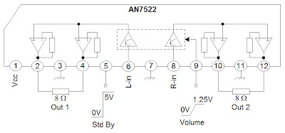 |
| Schematic AN7522 |
 |
| AN7523 amplifier schematic |
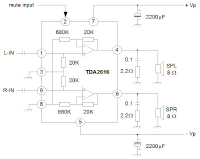 |
| Schematic TDA2616 |
Sunday, October 20, 2013
Power Failure and Low Line Signals
This is a circuit of Power-Fail and Low-Line Signals. This circuit is used to warn the processor when the power failure or a brownout is occurs. The processor will enter a power-down routine, when either of those signals interrupts the processor. Back up important data prior to the POR placing the processor in reset and cease its current activities are things that the processor do when enter the routine. Here is the circuit.Power-fail comparator is used to create a power-fail signal by monitoring the unregulated DC voltage. The regulator powers both supervisor circuit and the processor by using the the unregulated DC voltage.
Power-Failure and Low-Line Signals Schematic
 The regulator’s output capacitor retains its output voltage, so the unregulated voltage drops before the regulator’s voltage. And also, we can know drop in the regulator’s voltage. The processor can enter its power-down routine prior to being reset, if the power supply voltage were to drop low enough because of Detecting the regulator’s voltage drop.A supervisor provides a low-line signal, which goes active whenever the monitored power supply drops to a level slightly above the reset threshold so the processor can still receive warning of an imminent power failure when there is no access to the unregulated voltage.
To cause the POR to issue a reset, the processor warned that the power-supply voltage may decrease enough by the low-line signal. To anticipate the POR generating a reset, the processor backs up important data because of power failure or a brownout.
Power-Failure and Low-Line Signals Schematic
To cause the POR to issue a reset, the processor warned that the power-supply voltage may decrease enough by the low-line signal. To anticipate the POR generating a reset, the processor backs up important data because of power failure or a brownout.
Temperature protection using PTC and LM393
Used as a protective circuit above uses a component named PTC , the components in the operating obstacles , but obstacles desert PTC component is influenced by temperature, whereby if the cold temperatures of less than 100 degrees celcius , then this component has a few obstacles. And when temperature run to 100 degrees celcius or higher, which is owned PTC resistance will rise ass well. Because it depends on ambitient temperature , the PTC can be assembled into a circuit protection if high ambitient temperature, tand automatically switchess off, circuit like a schematic above.

R1___4K7
R2___10K
R3___1K9
R4___1M
R5___4k7
TH1__PTC thermistor
IC____LM393
Tuesday, October 15, 2013
Fire Alarm using NE555 and temperature sensor

This is a simple series of fire alarms. In this series used NE555 timer and temperature sensor to detect high temperatures. The working principle of this temperature sensor that is when the temperature is high around the sensor then there is resistance on the sensor to be small.
However if the low temperature then the resistance will be high. If the resistance of small sensors, the voltage supply will be able to flow past the sensor and activate the transistor.

IC1 NE555 as a regulator of the audio frequency. Transistors 1 and 2 are used as a driver IC1. Output (pin 3) of IC1 would trigger a transistor base T3 (SL100), which drives the speaker to produce sound the alarm. Frequency NE555 depending on resistance values of R5 and R6 and the capacitance sensor C2 temperature. When the temperature gets hot, would provide a low resistance so that supply voltage can flow into the base of transistor T1 through a diode D1 and R2.
Capacitor C1 will charge a positive voltage so that it will increase the time when the fire alarm. The greater the value of C1, the greater the positive bias applied to the base of transistor T1 (BC548). T1 collector coupled to the base transistor T2, transistor T2 provides a positive voltage to pin 4 (reset) from IC1 (NE555). Resistors R4 will make IC1 NE555 continued to be active despite no positive voltage flowing.
Monday, September 30, 2013
Relay Switch Activated by Tone and Signal
The essence of the circuit is for the input of tone and signal to provide an activation for the relay switch.
Circuit Diagram

The circuit created is sensitive enough to the AC signals in the input stage, where the signals are ranging above 5 mV. It will also be sensitive to react with the human voice signals having a range of frequency from 50 Hz up to 3 KHz. The human voice is a part of the human sound produced primarily by the vocal cords or vocal folds which in turn produces a voice frequency that is used for the transmission of speech.
During the absence of an input signal, the state of the 12 V relay RL1 is at OFF condition as regulated by the 10K Ohms trimmer RV1. The circuit can be made to react with its sensitivity in points A, B, & C, where a negative feedback can be placed due to the addition of band pass filter. The filter will operate only in the 1 KHz range and the circuit will only correspond at this frequency.
Parts List :

The signal and tone activated relay switch were used in a wide range of fields which includes measuring instruments, audio systems, communications equipment, and factory-automation equipment. They can also be found on telephone subscriber circuits for the polarity reversing switch, testing, and ringing functions.
- Relay – an electrically operated switch where the current flowing through the coil of the relay is creating a magnetic field which attracts a lever and changes the switch contacts, thereby making its state open or close
- BC214 – a complementary silicon planar epitaxial transistor used in AF small signal drivers and amplifiers as well as for low noise preamplifier applications due to its feature of good linearity of DC current gain
- LM741 – a general purpose single operational amplifier with features such as offset null, compensated internal frequency, voltage range with high input, good stability of temperature, and protected from short circuit
Circuit Diagram
The circuit created is sensitive enough to the AC signals in the input stage, where the signals are ranging above 5 mV. It will also be sensitive to react with the human voice signals having a range of frequency from 50 Hz up to 3 KHz. The human voice is a part of the human sound produced primarily by the vocal cords or vocal folds which in turn produces a voice frequency that is used for the transmission of speech.
During the absence of an input signal, the state of the 12 V relay RL1 is at OFF condition as regulated by the 10K Ohms trimmer RV1. The circuit can be made to react with its sensitivity in points A, B, & C, where a negative feedback can be placed due to the addition of band pass filter. The filter will operate only in the 1 KHz range and the circuit will only correspond at this frequency.
Parts List :
The signal and tone activated relay switch were used in a wide range of fields which includes measuring instruments, audio systems, communications equipment, and factory-automation equipment. They can also be found on telephone subscriber circuits for the polarity reversing switch, testing, and ringing functions.
Thursday, September 26, 2013
Technology Spending Limits and the Auto Sound System
We live in a world that is constantly changing and evolving. We see it every time we buy a new car, a new television, or a new computer. We see it every other month when the iPod is putting out a new an improved model that offers more features, more disk space, and more everything, in a smaller package (well not since they added video but until then, the gadgets were getting smaller while the features were growing exponentially). The truth of the matter is that technology seems to be advancing at a rate that is nearly impossible to keep up with. That being said, you can quite literally drive yourself insane by trying to keep up with the pace of modern technology.
What you need to do in order to maintain proper sanity is decide on a level of technology that you are comfortable and confident with and go with it until it is time (by either necessity or desire) to upgrade. You do not have to be the first to purchase the latest and greatest in software and gadgetry (this has become my mantra: I do not have to be the first to own the great big bad new toy, I will survive gadget deprivation-it isnt working yet but Im ever the optimist). The point is that you do not need to be the first to try every new thing and you will not only wear yourself out by trying but also you bank account, credit cards, and second mortgage. Technology is expensive, especially the newest and latest. If there was any doubt stroll on over to Ebay and see how much Play Station 3s are selling for at the moment-madness and lunacy do not even begin to subscribe the amount of money people are offering to pay for these devices.
Technology is a wonderful thing. It makes life easier for some and a lot more entertaining for others. The same holds true with auto sound systems. The technology exists to make them much more beneficial to car and driver than they have been in the past while offering many more features than ever before. Today you arent even limited to AM and FM. You now have the option of CDs, audio books, MP3s, XML, and digital FM radio, which offers a few bonus features over traditional radio. It really doesnt matter if you have the absolute latest. Most of us can enjoy a great deal of the wonderful technology that is available if we are willing to wait long enough for the prices to go down. I recall, and it wasnt all that long ago, when DVD players sold for no less than $100. You can get them now (about 5 years later) on a regular basis for less than $30. This is only one example of many. PS2s were around $400 when they first hit the market and now can be bought at the whopping price of $120. All around us technology evolves and grows and then prices fall.
The point is spend your money where you want to spend it rather than where you think it should be spent. If you want an auto sound system then get the best one that you feel meets your budget requirements. You do not have to have the top system in the technology food chain in order to have a great sound system that will provide you with years worth of enjoyment. You are the only one that is responsible for the decisions you make. It is up to you to decide where you want the bulk of your money invested when it comes to technological gadgets and goodies. Believe me, Im a gadget geek. I love playing with new toys and gizmos and seeing how they work-really, for me its a thrill. At the same time I realize I cant always be the first to get the new toys I so desperately want to try out so I limit myself and decide which ones are the most important. You must do this for yourself when it comes to auto sound systems.
Thursday, September 19, 2013
Police Lights Circuit with 555 and 4017 IC
This circuit uses a 555 timer which is setup to both runn in an Astable operating mode. This generates a continuous output via Pin 3 in the form of a square wave. When the timers output changes to a high state this triggers the a cycle on the 4017 4017 decade counter telling it to output the next sequential output high. The outputs of the 4017 are connected to the LEDs turning them on and off.
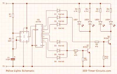 |
| Police Lights Circuit Schematic |
Wednesday, September 18, 2013
Evolving Technology and Auto Sound Systems
Finding auto sound systems that can keep up with the constantly evolving technology of today is a real challenge for many car and sound enthusiasts not only around the nation but also around the world. There was a time in the not so distant past when car stereos that had CD players or CD disc changers where the cutting edge of technology. New technology however has nearly rendered the CD players in cars as obsolete as long forgotten 8-track players. The sad news is that many carmakers are clinging to the old days and only offer something as modern as cassette players as standard equipment for auto sound systems.
I think those days will soon be forgotten, as cassettes are no longer even in mainstream production. You should also find that as CDs are rapidly becoming replaced by MP3s that take up very little space in our cars and homes, one day very soon we may see that music companies have decided it is no longer cost effective to produce CDs and render all music to digital formats. So, what does this mean for auto sound systems? Its actually good news for savvy manufacturers are well as savvy consumers who have their eyes on the future and the growing role technology is playing in our lives and as well as our commute to work.
Weve seen a recent introduction of satellite radio to our selection of auto sound systems. These stations offer the allure of no commercial interruptions to your music play in exchange for the price of a monthly subscription. At the moment there are two major companies that offer this service to consumers and each have rather proprietary equipment for their use and installation into your car. They are actually offering some rather tempting offers in order to encourage subscribers. Among those wonderful offers are auto sound systems for your vehicle at less than $100 with a prepaid year of subscription services.
For the satellite radio companies this indicates a constantly growing pool of prospective subscribers and the cost of the equipment is a drop in the bucket when compared to customer loyalty and being on the cutting edge of sound technology. The drawback is that you must decide which service you wish to go with before making the purchase. Also while they offer a very nice auto sound system (bare bones kind of kit that only allows for the radio reception in most cases) at a very sweet price, if you want upgrades such as MP3 compatibility, CD players, CD changers, DVD players, GPS, or any number of other new and advanced technology you will still have to purchase those for your sound system at an upgraded price. There are a few packages that come with these things, but the price is a little on the hefty side. Oh the sacrifices we will make for a more enjoyable daily commute.
Know what your expectations are before you decide to purchase the auto sound system of your dream or you could find that it is more the stuff that nightmares are made of than sweet dreams. Do not live in constant fear that if you buy today you will find something you like better 6 months from now, that is a reality. Technology is growing and evolving at a frightening pace. Find the auto sound system that you like best today and make that your purchase. This is a much better option than waiting around indefinitely and purchasing one just as your warranty expires on your car and its time for a trade in and another auto sound system.
Sunday, September 15, 2013
Digital Clock with Timer and Solar Panel Regulator
This is a combination digital clock timer and solar panel charge controller used to maintain a deep cycle battery from a solar panel. The timer output is used to control a 12 volt load for a 32 minute time interval each day. Start time is set using 9 dip switches and ends 32 minutes later. The 32 minute duration is set by selecting the 5th bit (2^5 = 32) of a 4040 binary counter (pin 2). The timer also has a manual toggle switch so the load can be manually switched on or off and automatically shuts off after 32 minutes. The time duration can be longer or shorter (8,16,32,64,128,256 minutes etc.) by selecting the appropriate bit of the counter. The timer circuit is shown in the lower schematic just above the regulator.
Basic Clock Circuit diagram
The basic clock circuit (top schematic below) is similar to the binary clock (on another page) and uses 7 ICs to produce the 20 digital bits for 12 hour time, plus AM and PM. A standard watch crystal oscillator (32,768) is used as the time base and is divided down to 1/2 half second by the 4020 binary counter. One half of a 4013 data latch is used to divide the 1/2 second signal by 2 and produce a one second pulse that drives the seconds counter (74HC390 colored purple). The minutes are advanced by decoding 60 seconds (40 + 20) and then resetting the seconds counter to 0 and at the same time advancing the minutes counter. The same procedure is used to advance the hours. The second half of the 4013 latch is used to indicate AM or PM and is toggled by decoding 13 hours and resetting the hours to 0 and then advancing the hours to "one".
Clock Display Circuit diagram
The clock display circuit is shown in the second drawing below and uses 6 more ICs to decode the binary data and drive four seven segment LED displays. The 10s of hours digit is driven with a single 3904 transistor. Two multiplexer circuits (4053) are used to manually select either minutes or seconds for the right two display digits. The two switches shown between the 4053s and below the left 4053 are both part of one DPDT switch which selects either seconds or minutes for the 1X and 10X digits. This switch is shown in the seconds position and the hours digits are blanked with a low signal on pin 4 of the 4511.
The display can also be toggled on and off (totally blank) using a set/reset latch made from a couple 74HC00 NAND gates. A momentary DPDT switch is used to control the latch and toggle the display on or off. The second pole of this switch is used on the upper drawing (connected to the run/stop switch) to set the hours and minutes. Thus this same switch performs both functions of blanking the display and setting the time. The run/stop switch is shown in the normal running mode and supplies a low signal to a NAND gate which prevents accidental setting the time while the clock is running.
Clock Timer Circuit diagram
The run/stop switch also turns on the display (through the diode D2) when in the stop position. The procedure for setting the clock would be to set the (run/stop) switch the stop position and the (seconds/minutes) switch to the minutes position. Then toggle the momentary switch to set minutes and hours of the current time plus one minute. The clock can then be started with the run/stop switch at precisely the right time (+/- 0.5 seconds).
Voltage Regulator (13.6 volts)
The voltage regulator in the lower drawing maintains the battery at 13.6 volts and also supplies the clock and timer circuits with 4.3 volts. The charge LED indicator only comes on when the regulator is supplying max charge to the battery. When the battery voltage reaches 13.6 the regulator reduces the current to whatever is necessary to maintain the voltage and the charge indicator will turn off. The unit I built also included a battery condition indicator (voltmeter using 4 LEDs) to indicate the battery condition so that a failure of the regulator would be indicated by the charge indicator LED turned off and less than 4 LEDs lit on the voltmeter.
Basic Clock Circuit diagram
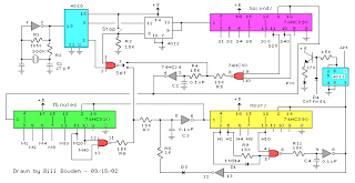 |
The basic clock circuit (top schematic below) is similar to the binary clock (on another page) and uses 7 ICs to produce the 20 digital bits for 12 hour time, plus AM and PM. A standard watch crystal oscillator (32,768) is used as the time base and is divided down to 1/2 half second by the 4020 binary counter. One half of a 4013 data latch is used to divide the 1/2 second signal by 2 and produce a one second pulse that drives the seconds counter (74HC390 colored purple). The minutes are advanced by decoding 60 seconds (40 + 20) and then resetting the seconds counter to 0 and at the same time advancing the minutes counter. The same procedure is used to advance the hours. The second half of the 4013 latch is used to indicate AM or PM and is toggled by decoding 13 hours and resetting the hours to 0 and then advancing the hours to "one".
Clock Display Circuit diagram
 |
The clock display circuit is shown in the second drawing below and uses 6 more ICs to decode the binary data and drive four seven segment LED displays. The 10s of hours digit is driven with a single 3904 transistor. Two multiplexer circuits (4053) are used to manually select either minutes or seconds for the right two display digits. The two switches shown between the 4053s and below the left 4053 are both part of one DPDT switch which selects either seconds or minutes for the 1X and 10X digits. This switch is shown in the seconds position and the hours digits are blanked with a low signal on pin 4 of the 4511.
The display can also be toggled on and off (totally blank) using a set/reset latch made from a couple 74HC00 NAND gates. A momentary DPDT switch is used to control the latch and toggle the display on or off. The second pole of this switch is used on the upper drawing (connected to the run/stop switch) to set the hours and minutes. Thus this same switch performs both functions of blanking the display and setting the time. The run/stop switch is shown in the normal running mode and supplies a low signal to a NAND gate which prevents accidental setting the time while the clock is running.
Clock Timer Circuit diagram
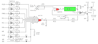 |
The run/stop switch also turns on the display (through the diode D2) when in the stop position. The procedure for setting the clock would be to set the (run/stop) switch the stop position and the (seconds/minutes) switch to the minutes position. Then toggle the momentary switch to set minutes and hours of the current time plus one minute. The clock can then be started with the run/stop switch at precisely the right time (+/- 0.5 seconds).
Voltage Regulator (13.6 volts)
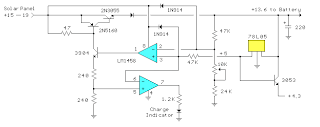 |
The voltage regulator in the lower drawing maintains the battery at 13.6 volts and also supplies the clock and timer circuits with 4.3 volts. The charge LED indicator only comes on when the regulator is supplying max charge to the battery. When the battery voltage reaches 13.6 the regulator reduces the current to whatever is necessary to maintain the voltage and the charge indicator will turn off. The unit I built also included a battery condition indicator (voltmeter using 4 LEDs) to indicate the battery condition so that a failure of the regulator would be indicated by the charge indicator LED turned off and less than 4 LEDs lit on the voltmeter.
Subscribe to:
Posts (Atom)