Showing posts with label led. Show all posts
Showing posts with label led. Show all posts
Thursday, November 14, 2013
Regulated Dual 3 Watt White LED Lamp
This project involves constructing an energy efficient dual 3 Watt white LED array that runs on 12VDC at 700mA. The lamp is useful for indoor indirect room lighting. The light that is produced does not flicker and has a regulated brightness from 11V to the maximum operating voltage. The Avago 3W white LEDs are rated at 3 watts (nominal). Never stare directly at this lamp when it is running at full operating power, it is dangerously bright.

Specifications:
The lamp is wired as a current loop which includes the power supply, the LED series string and the 700 mA current regulator circuit. The LM317 and 1.8 ohm 5 Watt resistor act as a current regulator that limits the loop current to 700 mA. Two 100nF monoblock capacitors bypasses the LM317 IC.
Construction:
The LEDs and current regulator circuit were mounted on a 3" x 6" piece of blank double-sided circuit board stock. The two LEDs and the LM317 regulator were soldered directly to the circuit board copper using a 200/240W soldering gun. The circuit board should be pre-tinned with solder and soldering should be done quickly to avoid overheating the parts.
The Avago LEDs come in several variations, the part used has an electrically isolated mounting tab, this feature is necessary for preventing a short circuit. If you cant find an LED with an isolated tab, be sure to mount each LED on its own isolated copper board. As of 2012, the specified LEDs are no longer available but there are plenty of other 700mA,3.7V white LEDs available. Just be sure to select one that you can easily solder to and connect to a heat sink.
The first version of this prototype ran too hot, so an aluminum heat sink was bolted to the board near the voltage regulator. Soldering the LM317 tab directly to the circuit board makes the board electrically hot at 1.8V, the board should not be allowed to come into contact with any live conductors. The LM317 may be optionally mounted on an insulated spacer to electrically isolate the board, in this arrangement, a TO-220 heat sink should be directly attached to the LM317.
The two resistors shown in the photo are combined in parallel to make a 1.8 ohm resistance, a single part would be a better choice. The entire circuit board can be mounted inside of a piece of aluminum "U" channel using plastic spacers for electrical isolation. The "U" channel reflects the bright light away from the side.
Use:
Connect this circuit to a 12VDC power supply or other power source such as a solar-charged lead acid battery. Be sure to observe the correct polarity. Look away from the LEDs and apply power. Again, do not stare directly at the LEDs. Prolonged exposure may harm your vision. A switch-mode power supply rated at 12VDC and 1 Amp or more is the most energy-efficient way to power one of these devices from line power. Your author liked this lamp so much that he constructed three of them to run in parallel and light his main electronics work bench.
Parts:
1x LM317 TO-220 case 1A adjustable voltage regulator
1x 1.8 ohm 5W resistor
2x 100nF 35V or higher monolythic capacitor
2x Avago ASMT-MYE2-NMN00 isolated tab 700mA,3.7V warm white LED or equivalent
3"x6" piece of double-sided copper circuit board stock
Miscellaneous wire, solder lugs, termination strips and hardware,
Large aluminum mounting plate, heat sinks if necessary.
Specifications:
- Nominal operating voltage: 12V DC
- Nominal operating current: 700 mA
- Maximum operating voltage: 16V DC
- Power consumption at 12.0V: 8.4W
- Minimum voltage for regulated light: 11V DC
- Leds produce light down to: 6V DC
- White LED voltage: 3.7V DC each
- White LED input power: 2.59 W each
- Voltage across regulator when current becomes regulated: 3.3V DC
The lamp is wired as a current loop which includes the power supply, the LED series string and the 700 mA current regulator circuit. The LM317 and 1.8 ohm 5 Watt resistor act as a current regulator that limits the loop current to 700 mA. Two 100nF monoblock capacitors bypasses the LM317 IC.
Construction:
The LEDs and current regulator circuit were mounted on a 3" x 6" piece of blank double-sided circuit board stock. The two LEDs and the LM317 regulator were soldered directly to the circuit board copper using a 200/240W soldering gun. The circuit board should be pre-tinned with solder and soldering should be done quickly to avoid overheating the parts.
The Avago LEDs come in several variations, the part used has an electrically isolated mounting tab, this feature is necessary for preventing a short circuit. If you cant find an LED with an isolated tab, be sure to mount each LED on its own isolated copper board. As of 2012, the specified LEDs are no longer available but there are plenty of other 700mA,3.7V white LEDs available. Just be sure to select one that you can easily solder to and connect to a heat sink.
The first version of this prototype ran too hot, so an aluminum heat sink was bolted to the board near the voltage regulator. Soldering the LM317 tab directly to the circuit board makes the board electrically hot at 1.8V, the board should not be allowed to come into contact with any live conductors. The LM317 may be optionally mounted on an insulated spacer to electrically isolate the board, in this arrangement, a TO-220 heat sink should be directly attached to the LM317.
The two resistors shown in the photo are combined in parallel to make a 1.8 ohm resistance, a single part would be a better choice. The entire circuit board can be mounted inside of a piece of aluminum "U" channel using plastic spacers for electrical isolation. The "U" channel reflects the bright light away from the side.
Use:
Connect this circuit to a 12VDC power supply or other power source such as a solar-charged lead acid battery. Be sure to observe the correct polarity. Look away from the LEDs and apply power. Again, do not stare directly at the LEDs. Prolonged exposure may harm your vision. A switch-mode power supply rated at 12VDC and 1 Amp or more is the most energy-efficient way to power one of these devices from line power. Your author liked this lamp so much that he constructed three of them to run in parallel and light his main electronics work bench.
Parts:
1x LM317 TO-220 case 1A adjustable voltage regulator
1x 1.8 ohm 5W resistor
2x 100nF 35V or higher monolythic capacitor
2x Avago ASMT-MYE2-NMN00 isolated tab 700mA,3.7V warm white LED or equivalent
3"x6" piece of double-sided copper circuit board stock
Miscellaneous wire, solder lugs, termination strips and hardware,
Large aluminum mounting plate, heat sinks if necessary.

Tuesday, November 5, 2013
Digital Led Chaser circuit diagram
 Digital Led Chaser circuit diagram
This particular circuit employs electronic digital circuits say for example a demultiplexer and also a binary table to build designs of "moving" led lights. This simple circuit is actually awesome while employed in the dark or light up an indicator of a few type, because it produces a awesome design which attracts the eyesight.
The primary component of the circuit is a demultiplexer 74ls138, we can be connected minimally important bits on the output on the counter, which will pick out one of many pins of the demultiplexer as being the output, lighting effects the led connected to the item. The counter can be wired only to be counted, plus a time clock beat is necessary to do that operate (the time clock circuit isnt involved, but almost any can do, if it is not very noisy)
One variation to apply is to connect the most major bit of that counter to a different a line leds, allowing and also disabling one of these so the design could observe 16 leds instead of the only 8 established these.
LED Lights circuits with LM339 IC555
This circuit reproduces the opening light sequence now used by FISA instead of Formula individual racing. It may possibly befall used with slot car sets (such like HO shin up AFX/Life Like/Tyco sets) or else means of communication controlled cars. IC1, a 555 timer IC, is used as a meter pulse generator. Its output is fed via NAND gates IC2a and IC2c to IC3, a 4024 binary counter. IC2b inverts the O4 output of 4024 binary counter IC3. at first, IC3 is reset and all its outputs are low, together with O4, which causes IC2b to grant a commonsensical climax to the pin 8 input of IC2c which afterward passes pulses from the 555 timepiece circuit to the clock input of the 4024. IC3 then begins including.
Similar to the count has reached binary 1111, the then pulse sends the O4 output of IC3 high, which disables IC2c and IC3 stops together with. The four used outputs of IC3 are connected to a resistor ‘ladder’ which acts because a undemanding digital to analog convert-er (DAC). As the count increases so does the voltage produced by the top of the ladder and this is connected to the inverting inputs of four comparators inside IC4 (an LM339) and to IC5, which is a 741 op amp besides connected for instance a comparator.

The certain inputs of the comparators are connected to the taps of a voltage barrier, with the drumming voltages frozen using VR1, a 100kO trimpot. As IC3 counts, the rising stepped voltage from the DAC ladder switches the comparators on during sequence, preparatory with IC4d and working up to IC5. because each one comparator is bowed on, its put together of LEDs is lit; essential LEDs 1 & 2, so therefore LEDs 3 & 4 and so on. at what time all five pairs of LEDs are lit, the after that pulse from IC1 moves the binary count of IC3 to 10000, so the DAC voltage drops back to zip and all LEDs are extinguished. by the same age, plus additionally stops, as the lofty on O4 causes IC2c to mass expand gate pulses. The circuit it follows that remains stationary until the counter is reset by burning pushbutton switch S1. This allows a new-fangled sequence to kick off.
Similar to the count has reached binary 1111, the then pulse sends the O4 output of IC3 high, which disables IC2c and IC3 stops together with. The four used outputs of IC3 are connected to a resistor ‘ladder’ which acts because a undemanding digital to analog convert-er (DAC). As the count increases so does the voltage produced by the top of the ladder and this is connected to the inverting inputs of four comparators inside IC4 (an LM339) and to IC5, which is a 741 op amp besides connected for instance a comparator.
The certain inputs of the comparators are connected to the taps of a voltage barrier, with the drumming voltages frozen using VR1, a 100kO trimpot. As IC3 counts, the rising stepped voltage from the DAC ladder switches the comparators on during sequence, preparatory with IC4d and working up to IC5. because each one comparator is bowed on, its put together of LEDs is lit; essential LEDs 1 & 2, so therefore LEDs 3 & 4 and so on. at what time all five pairs of LEDs are lit, the after that pulse from IC1 moves the binary count of IC3 to 10000, so the DAC voltage drops back to zip and all LEDs are extinguished. by the same age, plus additionally stops, as the lofty on O4 causes IC2c to mass expand gate pulses. The circuit it follows that remains stationary until the counter is reset by burning pushbutton switch S1. This allows a new-fangled sequence to kick off.
Wednesday, October 23, 2013
LM2901 LED bar graph meter
Several LED above and other components used to determine the signal amplifier, when in a state of high and low . If the signal received from the amplifier circuit is high then the LED lamp are lit up everything and more bright LED lamps, but otherwise if the received signal is low then the lights on only one or two , even absent or faint.
To use the circuit you can connec with the output amplifier or speaker output , if there is reinforcing the other in the amplifier , can be connected to the output.

Monday, October 7, 2013
LED Torch using NSI45090JDT4G Constant Current Regulator
A very simple LED torch can be designed using the NSI45090JDT4G adjustable constant current regulator (CCR) designed by ON Semiconductor ,using extreme few external components. NSI45090JDT4G device is designed to provide a cost effective solution for regulating current in LEDs. This Constant current regulator is based on patent-pending Self-Biased Transistor (SBT) technology and regulates current over a wide voltage range. It is designed with a negative temperature coefficient to protect LEDs from thermal runaway at extreme voltages and currents.
LED Torch Circuit Diagram

The Radj pin allows Ireg(SS) to be adjusted to higher currents by attaching a resistor between Radj (Pin 3) and the Cathode (Pin 4). The Radj pin can also be left open (No Connect) if no adjustment is required.The maximum current that can be adjusted using this chip is around 160 mA , and the maximum input voltage is around 45 volts The D1 from the circuit shown here is used for reverse battery protection .
Bellow you can see how simple is to design a circuit using this chip ( all data shown bellow are for this schematic ) .
LED’s = ((Vin − QX VF − D1 VF)/LED VF)
Example: Vin = 12 Vdc, QX VF = 3.5 Vdc, D1VF = 0.7 V
LED VF = 2.2 Vdc @ 30 mA
(12 Vdc − 4.2 Vdc)/2.2 Vdc = 3 LEDs in series.
LED Torch Circuit Diagram
The Radj pin allows Ireg(SS) to be adjusted to higher currents by attaching a resistor between Radj (Pin 3) and the Cathode (Pin 4). The Radj pin can also be left open (No Connect) if no adjustment is required.The maximum current that can be adjusted using this chip is around 160 mA , and the maximum input voltage is around 45 volts The D1 from the circuit shown here is used for reverse battery protection .
Bellow you can see how simple is to design a circuit using this chip ( all data shown bellow are for this schematic ) .
LED’s = ((Vin − QX VF − D1 VF)/LED VF)
Example: Vin = 12 Vdc, QX VF = 3.5 Vdc, D1VF = 0.7 V
LED VF = 2.2 Vdc @ 30 mA
(12 Vdc − 4.2 Vdc)/2.2 Vdc = 3 LEDs in series.
Tuesday, October 1, 2013
Alarm LED Light Circuit
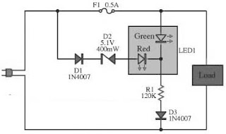
This circuit yearn for act the performance of the equipment,otherwise Check the fuse here the circuit.The circuit is diminutive and the power supply voltage of all kinds. It demonstrate with LED, 2-color in individual. Which is cathode universal kind,the anode has two separate terminals. If the circuit is functioning well LED, it revealed in wet behind the ears colour.The display is red, as the fuse into the circuit is damaged.The resistor R1 limits the current to gush through the LED is roughly 2 mA.This is an adequate amount to produce the LED light.If it lowers the R1 down, the LED light up.
 |
| Alarm LED Light Circuit Diagram |
In the conventional setup of the circuit and The fuse is not damaged. The zener diode to prevent the green and red LED illumination up in chorus.Zener diode prevents the LED is simple and red illumination all together.
The piercing efficiency LED, as soon as connected trendy like. The red LED uses high-pressure, so with the intention of single green LED illumination up only. Diodes D3 and D4 wish prevent dodgy instead of the LED. While the semi cycle downbeat voltage of the alternating current voltage.However, if the DC supply voltage.I act not retain to manage diode protection.
Wednesday, September 18, 2013
LED Flashlight Use Supercapacitor
Bored of playing around with capacitors? Then its time for you to move on to super-capacitors. These have huge storage capabilities. In this article you will find out how to build a small LED flashlight using supercapacitors.

The main disadvantage of capacitors is their large voltage drop. For this project, a minimum voltage of 2 volts is required to light the LED. As a result, the “Joule Thief” design would be incorporated here. Using this, a AA battery can be used to light an LED till it is completely discharged.
In this case, a supercapacitor would be taking the place of the battery. Here an LED is used to perform the function of a diode. This ensures that there is sufficient voltage across the LED.

The requirements of the project are listed below:
- White LED
- Super capacitor (10F, 2.7 V)
- Transistor
- Torus
- 1 k ohm resistor
- Wires
- Breadboard
The torus and the transistor used here comes from an energy-saving lamp HS. Care should be taken while removing this from the lamp as a breakage could result in the release of the mercury vapors. A lamp load along with a USB port is added to the circuit. This makes it compatible with a PC or a car radio.
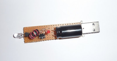
A few precautions have to be taken while constructing the circuit. The USB port should not be provided with excess power. The capacitor does not withstand a high voltage and hence a zener diode is connected in parallel to handle the high voltage. The diode protects the capacitor when the voltage exceeds a certain value.
Monday, September 16, 2013
6 Channel LED Driver Using MCP34845
A very simple 6 channel low cost led driver electronic circuit project can be designed using the MCP34845 LED drivers manufactured by Free scale Semiconductor.The MCP34845 LED drivers operates from 5 to 21 volts and is specially designed for use in back lighting LCD displays from 10" to 17"+ for devices like : PC Notebooks , Net books , Picture Frames , Portable DVD Players , Small Screen Televisions , Industrial Displays , Medical Displays , etc.
6 Channel LED Driver Circuit Diagram
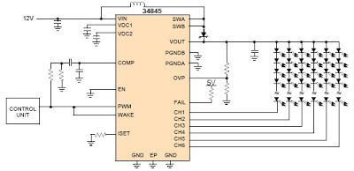
The MCP34845 LED drivers is capable of driving up to 16 LEDs in series in 6 separate strings.PWM dimming is performed by applying a PWM input signal to the PWM pin which modulates the LED channels directly.Main features of this driver circuit project are : input voltage of 5.0 to 21 V , boost output voltage up to 60 V, 2.0 A integrated boost FET , fixed boost frequency - 600 kHz or 1.2 MHz , OTP, OCP, UVLO fault detection , LED short/open protection , programmable LED current between 3.0 mA and 30 mA .
6 Channel LED Driver Circuit Diagram
The MCP34845 LED drivers is capable of driving up to 16 LEDs in series in 6 separate strings.PWM dimming is performed by applying a PWM input signal to the PWM pin which modulates the LED channels directly.Main features of this driver circuit project are : input voltage of 5.0 to 21 V , boost output voltage up to 60 V, 2.0 A integrated boost FET , fixed boost frequency - 600 kHz or 1.2 MHz , OTP, OCP, UVLO fault detection , LED short/open protection , programmable LED current between 3.0 mA and 30 mA .
Subscribe to:
Posts (Atom)