Showing posts with label stereo. Show all posts
Showing posts with label stereo. Show all posts
Sunday, November 17, 2013
Mini 2x75W Stereo Power Amplifier

 Your search for audio power amplifier with 75W stereo power with a slim body, you can use this Pyle - Mini 2x75W Stereo Power Amplifier - PCA3 . Power amp is designed simply and easily be placed anywhere, not just a good amplifier design is also very good in terms of sound quality in its gain. You can use this amplifier with a media player with a voice like VCD, DVD, Tape, etc.. What are you waiting you can buy the amplifier via the link below :
Stereo Low power audio amplifier

Audio amplifier circuit has a power output of 2 x 2.3 Watt, which uses IC KA2206, KA22061, LA4180, LA4182, LA4183, LA4550, LA4555, LA4558. The required voltage for at least 6 volts to 13 volts DC maximum. Component takes is a ic that I mentioned above one of them, and several capacitors elco.
This Schematics low power amplifier
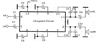
C1 = 1uF
C2 = 100uF
C3 = 100uF
C4 = 100uF
C5 = 0.1uF
C6 = 470uF
C7 = 1uF
C8 = 100uF
C8 = 100uF
C9 = 100uF
C10 = 100uF
C10 = 100uF
C11 = 0.1uF
C12 = 470uF
C12 = 470uF
ICs can use the ic which I mention above for each ic datasheet can be seen itself.
Friday, November 15, 2013
NJM2035 High Quality Stereo Encoder
High Quality Stereo Encoder with NJM2035


Technical Specifications:
Supply Voltage: 1.2V - 3.6V MAX
Current Draw:> 3mA
Channel Separation: <25 dB
Signal to Noise Ratio: 67 dB
Operation Temperature: -20 - 75 ° C
Frequency Range: 20Hz - 15KHz
Component List:
R 2x 47K
R 1x 10K
R 1x 82K
VR 1x 50K POT
C 1x 33uF
C 1x 10uF
C 3x 100nF (104)
C 1x 100pF (101)
C 1x 10pF (10)
1x IC IC NJM2035
1x XT 38 KHz Crystal
[Continue Reading]
This stereo encoder is the perfect solution for those looking for transmitting high quality stereo sound with low cost. This stereo encoder produces crystal clear stereo sound very good and very good channel separation that can match many more expensive stereo encoders that are available in the market.
Its all possible thanks to 38KHz quartz crystal that controls the 19kHz pilot tone, so youll never go back to calibrate or adjust sirkuit.NJM2035 offer superb quality and manufactured by NJR CORPORATION (JRC), a subsidiary of New Japan Radio, a company known as the worlds best manufacturers of high end professional audio semiconductors. This transmitter will work with mono FM transmitter including the TX300 and TX500 are available on our website. The entire series can easily fit on a small "x 1.5" printed circuit board that allows to adjust in a place where space is limited. While building your stereo encoder please take your time and always check with the scheme to ensure that all connections are done correctly.
Technical Specifications:
Supply Voltage: 1.2V - 3.6V MAX
Current Draw:> 3mA
Channel Separation: <25 dB
Signal to Noise Ratio: 67 dB
Operation Temperature: -20 - 75 ° C
Frequency Range: 20Hz - 15KHz
Component List:
R 2x 47K
R 1x 10K
R 1x 82K
VR 1x 50K POT
C 1x 33uF
C 1x 10uF
C 3x 100nF (104)
C 1x 100pF (101)
C 1x 10pF (10)
1x IC IC NJM2035
1x XT 38 KHz Crystal
How it Works
Stereo encoder consists of three main stages, pre-emphasis, digital encoder and mixer stages.
Pre-emphasis stage is achieved by using two 47K resistors and two capacitors 1NF. This helps to eliminate noise generated during the FM transmission of your audio signal.
The second stage is built around NJM2035 is a digital encoder. All internal blocks except for two audio amplifiers (pins 1 & 14) which acts as a separator made using digital circuits. The first digital circuit is a 38KHz oscillator generated by using external 38KHz crystal (pin 7), 10pF capacitor (pin 6) and 100pF bypass capacitor (pin 5). After 38KHz frequency generated is then buffered and divided into two 19KHz signals with a 180 degree phase difference. Once it is done two frequencies associated with two time division switching MPX digital alternating, one for each audio channel. Heres the audio channel is switched between each other with a total frequency of 38KHz. If you will be able to slow this frequency to 1Hz per second you will be able to hear that this trick is all but. During the first half of the two you will hear the left audio channel and in the second half the second you hear the right audio channel. Due to the fact that the channels are activated by a rapid frequency of 38KHz per second our brain can not recognize that this channel is really switched on and accept this as a continuous audio signal. At the same time another signal from the 38KHz oscillator is divided half to 19KHz. This signal is called a PILOT tone because it will help the stereo decoder in the receiver to slice MULTIPLEX signal (mixed L and R audio channels) and separate them back to the left and right channel audio.
The third stage is a mixer which consists of 33uF and 100nF capacitors and resistors are 82K and 10K. The role of this circuit is to mix the multiplex subcarrier and pilot signals together. The subcarrier multiplex signal coming out of Pin 9 of IC NJM2035 is the sum and difference of both left and right audio channels are activated at 38Khz. PILOT signal coming out of the pin 8 is the frequency of 19KHz that is used to distinguish what channel is currently switched on and without decoding stereo that will not be possible.
Tuesday, November 12, 2013
15W Stereo audio Amplifier using TDA 4935

TDA4935 2x15W audio amplifier is high quality Siemens IC. The IC can be used in stereo or bridge mode. In stereo mode can deliver 15W Stereo audio Amplifier using TDA 4935 per channel in bridge mode can deliver 30W to an 8 ohm load at the source of 30V. TDA4935 requires very few external components and has an ample supply voltage range. The IC operates in class B and has built-in protection circuits over temperature and overload protection.
Notes :
- The circuit must be assembled on a good quality PCB.
- TDA 4935 must be fitted with a proper heat sink.
- The supply voltage can be anything between 8 to 30V DC.
- Capacitors C1, C2, C8 are polyester capacitors.
- Capacitors C3, C4 and C6 are ceramic capacitors while C5 and C9 are electrolytic.
Saturday, November 9, 2013
AN7415 FM Stereo Demodulator

The circuit shown is a stereo FM PLL demodulator designed based on the AN7415. C1 is the input coupling capacitor to block any DC voltage present on the multiplexed input signal. LED D1 is an LED and R1 is the current limiting resistor. C4 and C5 are DC decoupling capacitors to the output channels left and right. C2 and C3 are bypass capacitors for noise output channels left and right. POT R2 can be used to adjust the separation between channels.
The resistor R5 and capacitors C7 and C8 form a network of low-pass filter for the internal DC amplifier circuit (see block diagram AN7415). C10 is a filter capacitor for the internal amplifier circuit Schmitt trigger IC. C9 is a filter capacitor for the circuit wave surge inside the AN7415. Resistor R3, R4 and capacitor C6 POT set the time constant of internal VCO circuit. Therefore POT R4 can be used to adjust the frequency of the VCO. A control signal 19KHz frequency is available in 12 pin IC. The switch S1 can be used to activate and deactivate the forced mono.
The resistor R5 and capacitors C7 and C8 form a network of low-pass filter for the internal DC amplifier circuit (see block diagram AN7415). C10 is a filter capacitor for the internal amplifier circuit Schmitt trigger IC. C9 is a filter capacitor for the circuit wave surge inside the AN7415. Resistor R3, R4 and capacitor C6 POT set the time constant of internal VCO circuit. Therefore POT R4 can be used to adjust the frequency of the VCO. A control signal 19KHz frequency is available in 12 pin IC. The switch S1 can be used to activate and deactivate the forced mono.
Tuesday, November 5, 2013
Stereo Audio Amplifier with IC TEA2024

The circuit above is based on IC TEA2024, package IC is SIP2-10 and manufactered by THOMSON. Circuit above can be applied anywhere as long as the speaker must be required , do not use powered speakers, it will make this circuit of hot , especially on the IC. So the use of powered speakers with the power output of this circuit.
Technical Information :Minimum voltage : 6 Volts DCMaximum voltage: 18Volts DCPower Output : 2 x 7 WattsImpedance : 4 OhmsCurrents : 35 mA
Monday, October 7, 2013
3000W Stereo Power Amplifier Circuit
Circuit Power Amplifier has a power output of up to 1500W RMS power amplifier circuit is often used to power sound systems keperlun for outdor. In the final image can be seen a series of power amplifiers using 10 sets of power transistors for the ending.
This power amplifier circuit using a transistor amplifier from the front, signal splitter, driver and power amplifier. Current consumption required is quite large power amplifier that is 15-20 A 1500W power amplifier circuits for this. Supply voltage needed by the power of this amplifier is the optimal working order symmetrical 130VDC (130VDC-130VDC ground). 1500W amplifier circuit below is a picture series of mono, stereo if you want to make it necessary to make two copies of the circuit. For more details can be viewed directly image the following 1500W power amplifier circuit.
The series of High Power Amplifier 1500W With Transistor
 |
| Click Image to view larger |
In the above series of power amplifer 1500W is equipped to control a DC Offset function to set the power amplifier is turned on at the moment and with no input signal then the output should be 0VDC. Then also equipped with a flow regulator to the power amplifier bias. Final part of this power amplifier requires adequate cooling to absorb the heat generated. Power amplifier is not equipped with a speaker protector, therefore it is necessary diapsang protector on the speaker output so that when the power amplifier is not the case turned on the beat to the speaker that can damage the speaker.
Saturday, October 5, 2013
Mono to Stereo Audio Signal Circuit Converter
This circuit is used to convert a mono audio signal into a stereo signal that can be panned between the left and right channel by a 0-10V control signal, it is intended for analog synthesizer systems.
 |
| Circuit Convert Mono to Stereo Audio Signal Schematic |
Tuesday, September 24, 2013
Low Voltage Stereo Headphone Amplifier
This is a stereo earphone amplifier circuit of using LM4910 IC. This circuit is very straightforward so it is very cool to comprise even in support of beginners after. for the reason that the voltage source is used solitary 3 VDC you can utilization 2 x A3 battery trendy progression stacking.
 |
| Low Voltage Stereo Headphone Amplifier |
LM4910 Boomer belonging to the series of state Semiconductors is an integrated stereo amplifier is primarily intended representing earphone stereo applications. The IC can come about operated from 3.3V ans its 0.35mW can release output power into a 32 ohm load. The LM4910 has very low distortion (minus than 1%) and the shutdown current is less than 1uA. This low shutdown current makes it as it should be designed for battery operated applications.
C1 and C2 are the input DC decoupling capacitors for the gone and due input channels. R1 and R2 are the respective input resistors. R3 is the feed back resistor representing not here channel while R4 is the feed back resistor for the right channel. C3 is the power supply filter capacitor. The criticism resistors as well sets the blocked ring expansion voguish conjunction with the corresponding input resistors.
Tuesday, September 17, 2013
200 Watt Stereo Car Amplifier
IC TA8210AH By using this you can apply a series of audio power amplifier is the car audio system. In general, all the speakers in the car using a subwoofer speaker, and woofer. Because the car is not big room so the sound is being required is not too high.
Audio amplifier circuit can work at a minimum voltage 12-volt DC, if supplied under voltage 12-volt amplifier work will be less than the maximum. This amplifier output power up to 200W or 2 x 100W stereo with 8 ohm impedance.
Audio amplifier circuit can work at a minimum voltage 12-volt DC, if supplied under voltage 12-volt amplifier work will be less than the maximum. This amplifier output power up to 200W or 2 x 100W stereo with 8 ohm impedance.
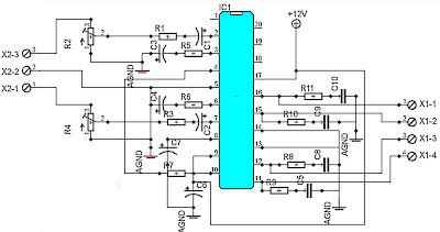
Part List :
R1 =1K
R2 =50K trim
R3 =1K
R4 =50K trim
R5 =680R
R6 =680R
R7 =150K
R8 =2R2
R9 =2R2
R10=2R2
R11=2R2
Capacitor
C1 =1uF
C2 =1uF
C3 =47uF
C4 =47uF
C5 =100n/400V
C6 =220uF
C7 =220uF
C8 =100n/400V
C9 =100n/400V
C10=100n/400V
Intregated Circuit
IC1=TA8210AH
Connector
X2-3=in R
X2-2=gnd
X2-1=in L
X1-1,X1-2=Out R
X1-3,X1-4=Out L
Monday, September 16, 2013
BTL Stereo Amplifier TDA7052 3
This is BTL stereo power amplifier with basic amplifier on IC TDA7052 / TDA7053

[Continue Reading]
Subscribe to:
Posts (Atom)