Showing posts with label controller. Show all posts
Showing posts with label controller. Show all posts
Saturday, November 16, 2013
Volume Controller Equalizer Using LM1036
This volume controller equalizer electronic project is designed using LM1036 DC tone volume controller with volume and balance circuit for stereo applications .An additional control input of the LM1036 allows loudness compensation to be simply effected.
Volume Controller Equalizer Circuit Using LM1036

The four control inputs of the LM1036 volume controller provides control of the bass, treble, balance and volume functions through application of DC voltages from a remote control system or, alternatively, from four potentiometers which may be biased from a zenner regulated supply provided on the circuit.Each tone response is defined by a single capacitor chosen to give the desired characteristic.
Volume Controller Equalizer Circuit Using LM1036

Sunday, November 3, 2013
DC Fan Controller
This circuit is ideal to control the cooling fan of heat generated electronic gadgets like power amplifiers. The circuit switches on a fan if it senses a temperature above the set level. The fan automatically turns off when the temperature returns to normal.
The circuit uses an NTC (Negative Temperature Coefficient) Thermister to sense heat. NTC Thermister reduces its resistance when the temperature in its vicinity increases.IC1 is used as a voltage comparator with two potential dividers in its inputs. Resistor R1 and VR1 forms one potential divider connected to the non inverting input of IC1 and another potential divider comprising R2 and the 4.7K Thermister supplying a variable voltage to the inverting input of IC1. VR1 is adjusted so as to give slightly lesser voltage at the non inverting input than the inverting input at room temperature.
DC Fan Controller Circuit diagram:

In this state, output of IC1 will be low and the Fan remains off. When the temperature near the Thermister increases, its resistance decreases and conducts. This drops the voltage at pin 2 of IC1 and its output becomes high. T1 then triggers and fan turn on. Red LED indicates that fan is running. Capacitor C1 gives a short lag before T1 turns on to avoid false triggering and to give proper bias to T1.DC fan can be the one used in Computer SMPS.
Keep the Thermistor near the heat sink of the Amplifier PCB and switch on the amplifier for 10 minutes. Then adjust VR1 till the Fan stop running.When the temperature rises, Fan will automatically switch on.
The circuit uses an NTC (Negative Temperature Coefficient) Thermister to sense heat. NTC Thermister reduces its resistance when the temperature in its vicinity increases.IC1 is used as a voltage comparator with two potential dividers in its inputs. Resistor R1 and VR1 forms one potential divider connected to the non inverting input of IC1 and another potential divider comprising R2 and the 4.7K Thermister supplying a variable voltage to the inverting input of IC1. VR1 is adjusted so as to give slightly lesser voltage at the non inverting input than the inverting input at room temperature.
DC Fan Controller Circuit diagram:
In this state, output of IC1 will be low and the Fan remains off. When the temperature near the Thermister increases, its resistance decreases and conducts. This drops the voltage at pin 2 of IC1 and its output becomes high. T1 then triggers and fan turn on. Red LED indicates that fan is running. Capacitor C1 gives a short lag before T1 turns on to avoid false triggering and to give proper bias to T1.DC fan can be the one used in Computer SMPS.
Keep the Thermistor near the heat sink of the Amplifier PCB and switch on the amplifier for 10 minutes. Then adjust VR1 till the Fan stop running.When the temperature rises, Fan will automatically switch on.
Saturday, October 26, 2013
Stepper Motor Controller Using by A3952S
Using the A3952S stepper motor controller ( designed by Allegro MicroSystems ) we can design a very simple and useful motor driver circuit that can be used in many electronic applications . A3952S stepper motor controller is capable of continuous output currents up to 2 A and operating voltages range up to 50 V. Internal fixed off-time PWM current-control circuitry can be used to regulate the maximum load current to a desired value. The MODE terminal can be used to optimize the performance of the device in microstepping / sinusoidal stepper motor drive applications.
A3952S Stepper Motor Controller Circuit diagram

When the average load current is increasing, slow-decay mode is used to limit the switching losses in the device and iron losses in the motor. The thermal performance in applications with high load currents and/or high duty cycles can be improved by adding external diodes in parallel with the internal diodes. In internal PWM slow-decay applications, only the two top-side (flyback) diodes need be added. For internal fast-decay PWM, or external PHASE or ENABLE input PWM applications, all four external diodes should be added for maximum junction temperature reduction .
As you can see in the schematic diagram , this stepper motor driver circuit require two A3952S circuits and other few additional electronic components.
A3952S Stepper Motor Controller Circuit diagram
As you can see in the schematic diagram , this stepper motor driver circuit require two A3952S circuits and other few additional electronic components.
Wednesday, October 9, 2013
Electronic Smart Heater Controller
Minuscule circuit of the electronic heater controller presented here is built around the renowned 3-Pin Integrated Temperature Sensor LM35 (IC1) from NSC. Besides, a popular Bi Mos Op-amp CA3140 (IC2) is used to sense the status of the temperature sensor IC1, which also controls a solid-state switch formed by a high power Triac BT136(T1). Resistive type electric heater at the output of T1 turns to ON and to OFF states as instructed by the control circuit.
This gadget can be used as an efficient and safe heater in living rooms, incubators, heavy electric/electronic instrument etc. Normally, when the temperature is below a set value (Decided by multi-turn preset pot P1), voltage at the inverting input (pin2) of IC1 is lower than the level at the non-inverting terminal (pin3). So, the comparator output (at pin 6) of IC1 goes high and T1 is triggered to supply mains power to the desired heater element.
Electronic Heater Controller Circuit diagram:

Note: CA3140 (IC2) is highly sensitive to electrostatic discharge (ESD). Please follow proper IC Handling Procedures.
When the temperature increases above the set value, say 50-60 degree centigrade, the inverting pin of IC1 also goes above the non-inverting pin and hence the comparator output falls. This stops triggering of T1 preventing the mains supply from reaching the heater element. Fortunately, the threshold value is user-controllable and can be set anywhere between 0 to 100 Degree centigrade.
The circuit works off stable 9Volt dc supply, which may be derived from the mains supply using a standard ac mains adaptor (100mA at 9V) or using a traditional capacitive voltage divider assembly. You can find such power circuits elsewhere in this website.
This gadget can be used as an efficient and safe heater in living rooms, incubators, heavy electric/electronic instrument etc. Normally, when the temperature is below a set value (Decided by multi-turn preset pot P1), voltage at the inverting input (pin2) of IC1 is lower than the level at the non-inverting terminal (pin3). So, the comparator output (at pin 6) of IC1 goes high and T1 is triggered to supply mains power to the desired heater element.
Electronic Heater Controller Circuit diagram:
Note: CA3140 (IC2) is highly sensitive to electrostatic discharge (ESD). Please follow proper IC Handling Procedures.
When the temperature increases above the set value, say 50-60 degree centigrade, the inverting pin of IC1 also goes above the non-inverting pin and hence the comparator output falls. This stops triggering of T1 preventing the mains supply from reaching the heater element. Fortunately, the threshold value is user-controllable and can be set anywhere between 0 to 100 Degree centigrade.
The circuit works off stable 9Volt dc supply, which may be derived from the mains supply using a standard ac mains adaptor (100mA at 9V) or using a traditional capacitive voltage divider assembly. You can find such power circuits elsewhere in this website.
Sunday, October 6, 2013
Making PC USB LCD controller project
 This really a work that so cool if you like modif PC. So this is a USB interface for alphanumeric LCD display like 4 × 20 which can be controlled with LCD Smartie program. USB interface is implemented by using PIC18F2550 microcontroller, Using USB LCD modules. Below is a project of the USB LCD controller.
Schematic circuit and PCB design

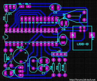
source | link
Audio Level Controller
The following schematic illustrates the clean Audio Level Controller Circuit Diagram designed and produced by SHURE microphones and electronics components. All the capacitors trendy MFD except given away otherwise and working voltages above 100 except given away. All resistors 10% tolerance. The selected resistor is chosen to adjust time someplace regulating battle starts to corresponds to distance selector switch settings.
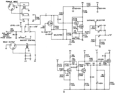 |
| Audio Level Controller Circuit Diagram |
Monday, September 16, 2013
10 Amp Solar Charge Controller
The SCC2 is a solar charge controller, its function is to regulate the power flowing from a photovoltaic panel into a rechargeable battery. It features easy setup with one potentiometer for the float voltage adjustment, an equalize function for periodic overcharging, and automatic temperature compensation for better charging over a range of temperatures.
10 Amp Solar Charge Controller Circuit Diagram with Parts List

The goal of the circuit design was to make a charge controller with analog simplicity, high efficiency, and reliability. A medium power solar system can be built with a 12V solar panel up to 10 amps, the SCC2, and a rechargeable battery. The SCC2 works with lead acid, NiCD and NiMH batteries with ratings from less than one to several hundred amp-hours. With the appropriate parts selection, the SCC2 can be operated at 6V, 12V, 24V or other voltages.
Specifications:
The SCC2 acts as a medium power DC current switch between the + terminals of the PV and battery. Diode D1 prevents reverse night time current flow from the battery back to the PV panel.
When the PV voltage is high enough to charge the battery, zener diode D2 conducts and turns on transistor Q2. Q2 switches the power for the rest of the circuit on. The circuit is switched off at night. IC2 provides a 5 volt regulated voltage to power the comparator circuits, it also provides a reference voltage for comparator IC1a.
When the battery voltage is below the desired full voltage and needs charging, comparator IC1a turns on and activates Q1 and Q3, this allows the solar charging current to flow into the battery. Note that Q3 is a P-channel mosfet, this allows the circuit to be wired with a common ground for the solar panel and battery. The solar current loop is drawn in heavy lines on the schematic.
When the battery reaches the full charge point, IC1a operates as a comparator based schmidt trigger oscillator, it switches the solar current off and on. The switching causes the battery voltage to oscillate a few tens of millivolts above and below the desired set point. A rail-to-rail op-amp is required for proper operation, 741 style op-amps will not work in this circuit.
The red/green charging/full LED is driven between the output of IC1a and IC1b. IC1b has an inverted version of the IC1a signal. Pin 5 of IC1b only needs an approximate center point to work as an on-off comparator, it is connected to the varying IC1a pin 2 so that it does not require another reference divider circuit.
The resistors and thermistor on the input side of IC1a form a resistive bridge circuit that is used to compare the battery voltage to a reference voltage coming from IC2/R8/R9. The potentiometer adjusts the voltage point around which the circuit will oscillate on full charge. Resistor R7 adds positive feedback to IC1a for a schmidt trigger characteristic and C6 sets the maximum frequency of oscillation. The thermistor provides thermal compensation, as the temperature goes down, the float voltage setting goes up.
The equalize switch, S1a, forces the circuit on for intentional overcharging. Switch S1b and R1 can be used to select a different float voltage range, you can experiment with this by using different values of R1, typically R1 should be greater than 1M.
Alignment:
Connect the solar panel to the SCC2 solar panel input connectors, connect the battery to the SCC2 output connectors. Put the solar panel in the sun, and watch the battery charge up. Systems where the battery is frequently discharged way down should occasionally be run in equalize mode for a few hours or a full day. It is best to monitor the battery voltage during this operation, disable equalization if the battery voltage goes above 16V (12V version).
10 Amp Solar Charge Controller Circuit Diagram with Parts List
The goal of the circuit design was to make a charge controller with analog simplicity, high efficiency, and reliability. A medium power solar system can be built with a 12V solar panel up to 10 amps, the SCC2, and a rechargeable battery. The SCC2 works with lead acid, NiCD and NiMH batteries with ratings from less than one to several hundred amp-hours. With the appropriate parts selection, the SCC2 can be operated at 6V, 12V, 24V or other voltages.
Specifications:
- Maximum solar panel current: 10 Amps
- Night time battery drain current: approximately 1ma
- Nominal battery voltage: 6V, 12V or 24V.
- See the full SCC2 specifications for more information.
The SCC2 acts as a medium power DC current switch between the + terminals of the PV and battery. Diode D1 prevents reverse night time current flow from the battery back to the PV panel.
When the PV voltage is high enough to charge the battery, zener diode D2 conducts and turns on transistor Q2. Q2 switches the power for the rest of the circuit on. The circuit is switched off at night. IC2 provides a 5 volt regulated voltage to power the comparator circuits, it also provides a reference voltage for comparator IC1a.
When the battery voltage is below the desired full voltage and needs charging, comparator IC1a turns on and activates Q1 and Q3, this allows the solar charging current to flow into the battery. Note that Q3 is a P-channel mosfet, this allows the circuit to be wired with a common ground for the solar panel and battery. The solar current loop is drawn in heavy lines on the schematic.
When the battery reaches the full charge point, IC1a operates as a comparator based schmidt trigger oscillator, it switches the solar current off and on. The switching causes the battery voltage to oscillate a few tens of millivolts above and below the desired set point. A rail-to-rail op-amp is required for proper operation, 741 style op-amps will not work in this circuit.
The red/green charging/full LED is driven between the output of IC1a and IC1b. IC1b has an inverted version of the IC1a signal. Pin 5 of IC1b only needs an approximate center point to work as an on-off comparator, it is connected to the varying IC1a pin 2 so that it does not require another reference divider circuit.
The resistors and thermistor on the input side of IC1a form a resistive bridge circuit that is used to compare the battery voltage to a reference voltage coming from IC2/R8/R9. The potentiometer adjusts the voltage point around which the circuit will oscillate on full charge. Resistor R7 adds positive feedback to IC1a for a schmidt trigger characteristic and C6 sets the maximum frequency of oscillation. The thermistor provides thermal compensation, as the temperature goes down, the float voltage setting goes up.
The equalize switch, S1a, forces the circuit on for intentional overcharging. Switch S1b and R1 can be used to select a different float voltage range, you can experiment with this by using different values of R1, typically R1 should be greater than 1M.
Alignment:
- Start with a charged battery, connect the solar panel directly to the battery until the battery voltage is at or above the desired full setting, this also that the panel is capable of charging the battery.
- While measuring the battery voltage, adjust VR1 clockwise to align the float voltage set point. If the LED turns red before it reaches the desired float voltage, the battery will need to charge for a while.
- When the battery is fully charged, it should be at the float voltage and the led should show alternating colors.
- The float voltage should be set when the board and battery are at room temperature. Typical 12V set points are 13.8V for a gell cell and 14.5V for a wet cell. For 6V, divide those by two, for 24V, multiply by 2.
- Follow your battery manufacturers recommendations for the best settings.
- Readjust the float voltage after the battery has reached a full charge.
- The float voltage should be set when the circuit is at room temperature.
Connect the solar panel to the SCC2 solar panel input connectors, connect the battery to the SCC2 output connectors. Put the solar panel in the sun, and watch the battery charge up. Systems where the battery is frequently discharged way down should occasionally be run in equalize mode for a few hours or a full day. It is best to monitor the battery voltage during this operation, disable equalization if the battery voltage goes above 16V (12V version).
Subscribe to:
Posts (Atom)