Showing posts with label for. Show all posts
Showing posts with label for. Show all posts
Saturday, November 16, 2013
Tips for caring power supply units
 Power Supply on a computer is an energy source that drives the computer you. With power supply, hardware on the computer is given "power" to can work in accordance with their respective functions Power Supply on a computer to work as a flow modifier (Adapter) from AC current into DC.
 Power supply is working on 2 pieces of 5-volt DC voltage and 12 Volt. In a power supply, voltage 12 volt is usually characterized with a yellow cable, while the voltage is 5 Volt is marked with cable red.

Tips to maintain power supply in order to remain durable
1. Make sure you buy the power supply to suit your computer needs. Buy power supply that is guaranteed quality.
2. Make sure when you install a power supply on your computer already in the correct position. Make a tightening of the socket-outlet power supply to the motherboard, hard drive, CDRom, etc.. If you do the installation is not correct it will be fatal and can be a fire or a short-circuit will occur on your hardware.
3. Check your power supply voltages in the BIOS Hardware Monitor or Hardware Management. Is it permissible range qualified. If it does not fit will usually be marked with red writing.
4. Check the condition of the fan at any time at least 3 months. Or, when you have a problem on your computer such as Hang, Restart and Total death. Clean the fan if necessary and give a lubricant (contact cleaner) in as a fan.
5. Do not put your CPU is too close (mepet) with the wall. Because it would cause air circulation fan should be running with the operation will be disrupted.
1. Make sure you buy the power supply to suit your computer needs. Buy power supply that is guaranteed quality.
2. Make sure when you install a power supply on your computer already in the correct position. Make a tightening of the socket-outlet power supply to the motherboard, hard drive, CDRom, etc.. If you do the installation is not correct it will be fatal and can be a fire or a short-circuit will occur on your hardware.
3. Check your power supply voltages in the BIOS Hardware Monitor or Hardware Management. Is it permissible range qualified. If it does not fit will usually be marked with red writing.
4. Check the condition of the fan at any time at least 3 months. Or, when you have a problem on your computer such as Hang, Restart and Total death. Clean the fan if necessary and give a lubricant (contact cleaner) in as a fan.
5. Do not put your CPU is too close (mepet) with the wall. Because it would cause air circulation fan should be running with the operation will be disrupted.

Friday, November 15, 2013
Cheap Electronics Component for Amplifier Application

Cheap electronics component for amplifier application, it is simple to be made for speaker active . The sound quality even this Mini Amplifier TDA2030 quite satisfactory for a portable audio system.
"The series of Mini Amplifier TDA 2030 "The series of mini amplifie can reproduce the power output of 14 Watt with 8 Ohm speaker load. The series of mini-amplifier can be supplied with ource voltage of 12 volts - 15 volts DC. more details, see the following series of pictures.
"The series of Mini Amplifier TDA 2030 "The series of mini amplifie can reproduce the power output of 14 Watt with 8 Ohm speaker load. The series of mini-amplifier can be supplied with ource voltage of 12 volts - 15 volts DC. more details, see the following series of pictures.

Daftar komponen
Resistor:
- R1: 150KΩ
- R2: 4.7KΩ
- R3: 100KΩ
- R4: 1Ω 1W
- RA/RB: 100KΩ
Capacitor
- C1: 1µF / 25V
- C2: 2.2µF / 25V
- C3: 100nF
- C4: 22µF / 25V
- C5: 100 µF / 25V
- C6: 220nF
- C7: 2200µF / 35V
IC / Dioda
- IC1: TDA2030 or TDA2030a
- D1/D2: IN4002
Wednesday, November 13, 2013
XM Satellite Radio Vs Sirius for your Auto Sound System Selection
If youre in the market for a new auto sound system you might want to seriously take a moment and consider whether or not you would be benefited by subscribing to either Sirius or XM Satellite Radio. Both of these subscription-based services have something wonderful to offer their subscribers and both of them require specialized equipment in order to operate. This means if you are going to wish to use either service, you will need to have decided which service before you have your auto sound system installed.

It really doesnt matter which of these you choose they each have different features that will appeal to a wide variety of audiences. You will find some wonderful competition among the two not only by way of music radio but also talk radio. If you really love talk radio you really need to subscribe to one of these in order to find a treasure chest of talk radio gems. You will find everything from the mundane to the controversial. From Oprah to Howard Stern exist in the realm of satellite radio, which seems to not only be catching on but also here to stay.
It has been commented on many times that XM Satellite Radio has a strong lead when it comes to subscriptions. This is very true but you should also keep in mind that the new subscribers seem to be leaning more towards Sirius for their satellite radio rather than going with the traditional favorite. Ive checked out the line up and cant see that one has much of a clearly defined lead over the other so I cant give a definitive reason for the massive new subscribers to Sirius or even the phenomenal lead that XM Satellite radio is currently enjoying. Regardless if this is something that might interest you, you really should check out each website and decide for yourself which, if either, is more appealing to you as well as whether that appeal is worth the investment and the monthly subscription fee.
I will say this however: XM Satellite Radio for the moment seems to have much better toys to offer consumers. That being said, Im actually quite surprised that the vast number of new subscribers are going with Sirius rather than XM. Of course, being the gadget geek that I am, I am basing that surprise solely on the fact that XM seems to have much better toys. At the moment XM is offering some really cool gadgets that double not only as XM Satellite Radio receivers but also offer GPS functionality and navigation assistance and controls. Some of these devices even go one step further and play DVDs, CDs, MP3s, among other things.
Believe me, Sirius has a lot to offer its customers as well, Im simply thrilled over select items that can be found at XM that I really havent seen adequate competition for elsewhere. On the level of music, both seem to carry similar genres, lineups, etc. The same holds true for the Talk radio line up. The only major difference I am finding between the two are the gadgets. Even the prices are rather competitive with one another. I see only one other major difference and that is the fact that Sirius offers a lifetime membership that cost about the same as the five-year plan from XM Satellite Radio. The thing to remember however is that the lifetime membership is for the lifetime of the device not the subscriber.
I should also point out that opting for satellite radio more than likely will not eliminate your need for a new auto sound system it may however pose certain requirements for the type of sound system you will be able to choose. One thing I have noticed with both companies is that there are plenty of devices from which to choose. You will have your hands full selecting the right equipment for your auto sound system upon which to enjoy the wonderful sounds that satellite radio will bring to your ears each and every day.
Friday, November 8, 2013
Alarm Indicator for High Temperature Reading
The circuit has been designed to provide an alarm with the use of a buzzer when sensing high temperature by using a thermistor.
These bipolar transistors form a Darlington pair to produce a very high current gain that is much higher then each transistor taken separately. This is made possible when the current amplified by the first transistor is further amplified by the second transistor. The overall gain is equal to the two individual gains multiplied together.A Darlington pair is designed in such a way that the collectors of both transistors are attached together and the emitter of the first transistor is directly coupled to the base of the second or output transistor. The base current of the output transistor is equal to the emitter current of the input transistor. When several transistors are used, it can form a cascade connection and the total current amplification factor will be very high since it is a product of current amplification factor of respective transistors.
Alarm Indicator for High Temperature Reading Schematic

When the Darlington pair conducts in this circuit, it causes the relay K1 to close thereby triggering the buzzer to produce sound due to the increase in temperature that is more than the predetermined value. The location of the thermistor should be far enough from other components of the circuit to prevent inhibiting their temperature. The circuit is powered by a 9 V battery for ease of transportation but a dedicated power supply can be provided is the circuit would be in a permanent location. A load, like a lamp or a LED, can also be connected to the contacts of the relay to produce a light indication or notification of the occurrence of excess temperature. Since the circuit is well insulated, the thermistor, connected to the circuit with a plated cable, can be submerged to water to cool down or reset the sensitivity and will not cause any short circuit. Doing this will regulate the trimmer.
This circuit can be designed not only by setting a detection of high temperature but can also be modified to be set on detection of low temperature in some industries. It can be used for refrigeration, walk-in freezer, or walk-in cooler systems and other environments that are sensitive in temperature. Some circuits incorporating high temperature alarm modules are being used in motor vehicles to detect the occupancy wherein the temperature element senses a highly dangerous temperature in the passenger compartment of a motor vehicle and energizes the occupancy sensor to determine the presence or absence of an occupant. In the absence of the occupant, the sensor de-energizes after a period of time while an audible alarm is triggered to create attention to the motor vehicle in the presence of an occupant. This type of alarm can be reset with the use of a key.
Having a temperature alarm can provide benefits like protecting valuable equipment due to high temperature, low temperature, or sometimes high humidity. Other high temperature program can be used to protect against air conditioning failure or against the heating system to turn off. On the contrary, low temperature program can be used against heating system failure by aiding to prevent frozen pipes. The alarm can also reduce downtime by receiving a telephone call and being notified of a possible power loss or failure before the damage occurs in an equipment.

The Darlington pair used in the circuit can also be used as an important component in a switching device while high power Darlington transistors can be used in emergency power supply and in control circuits for AC and DC motor control. These applications make the Darlington suitable for switching large currents in high power circuits.
- Thermistor – one type of resistor used as temperature-sensing element which demonstrates a large change in resistance proportional to a small change in temperature because of the composition of its semiconductor material.
- BC550 – an NPN general purpose transistor with low current and low voltage used for low noise stages in audio frequency equipment.
These bipolar transistors form a Darlington pair to produce a very high current gain that is much higher then each transistor taken separately. This is made possible when the current amplified by the first transistor is further amplified by the second transistor. The overall gain is equal to the two individual gains multiplied together.A Darlington pair is designed in such a way that the collectors of both transistors are attached together and the emitter of the first transistor is directly coupled to the base of the second or output transistor. The base current of the output transistor is equal to the emitter current of the input transistor. When several transistors are used, it can form a cascade connection and the total current amplification factor will be very high since it is a product of current amplification factor of respective transistors.
Alarm Indicator for High Temperature Reading Schematic
When the Darlington pair conducts in this circuit, it causes the relay K1 to close thereby triggering the buzzer to produce sound due to the increase in temperature that is more than the predetermined value. The location of the thermistor should be far enough from other components of the circuit to prevent inhibiting their temperature. The circuit is powered by a 9 V battery for ease of transportation but a dedicated power supply can be provided is the circuit would be in a permanent location. A load, like a lamp or a LED, can also be connected to the contacts of the relay to produce a light indication or notification of the occurrence of excess temperature. Since the circuit is well insulated, the thermistor, connected to the circuit with a plated cable, can be submerged to water to cool down or reset the sensitivity and will not cause any short circuit. Doing this will regulate the trimmer.
This circuit can be designed not only by setting a detection of high temperature but can also be modified to be set on detection of low temperature in some industries. It can be used for refrigeration, walk-in freezer, or walk-in cooler systems and other environments that are sensitive in temperature. Some circuits incorporating high temperature alarm modules are being used in motor vehicles to detect the occupancy wherein the temperature element senses a highly dangerous temperature in the passenger compartment of a motor vehicle and energizes the occupancy sensor to determine the presence or absence of an occupant. In the absence of the occupant, the sensor de-energizes after a period of time while an audible alarm is triggered to create attention to the motor vehicle in the presence of an occupant. This type of alarm can be reset with the use of a key.
Having a temperature alarm can provide benefits like protecting valuable equipment due to high temperature, low temperature, or sometimes high humidity. Other high temperature program can be used to protect against air conditioning failure or against the heating system to turn off. On the contrary, low temperature program can be used against heating system failure by aiding to prevent frozen pipes. The alarm can also reduce downtime by receiving a telephone call and being notified of a possible power loss or failure before the damage occurs in an equipment.
The Darlington pair used in the circuit can also be used as an important component in a switching device while high power Darlington transistors can be used in emergency power supply and in control circuits for AC and DC motor control. These applications make the Darlington suitable for switching large currents in high power circuits.
Friday, November 1, 2013
Automatic Switch for Batteries
Nowadays the batteries are gaining more and more power, being the only components that fail to provide energy for portable electronic devices. The evolution is rapid, leading manufacturers electronic equipment to attempt to minimize the consumption of their products so that they can operate for several hours using simple batteries trade. In spite of the efforts of manufacturers, the device will absorb a zero power not yet invented. Thus, both small and if the current device is mathematically certain that at some point, after a few hours, days or ethdomades, the battery-drain .
Automatic Switch for Batteries Circuit diagram
 The purpose of the circuit will describe below, is to keep alive batteries for the maximum time, minimizing unnecessary consumption. Taking a brief look at the circuit, you notice that the few parts that are can be integrated into any device powered by a battery of 9 V. The main trait is that allows current to flow to the load for a minute, since you pressed the switch S1. After this time automatically cuts off the battery connection. The peak current during switching is 20 mA, price satisfactory for most devices that work with batteries, this nominal voltage.
The heart of the construction is a Darlington type transistor PNP (T1), which is driven in a state of conduction through the pressing switch S1. The small current thaoio, which is due to the high rate of aid, makes able to remain in this condition even for relatively small values ??of the capacity of capacitor C 1 (Around 100 MF). The resistance A3 limits the charge current of the capacitor, thus ensuring long life pressing the switch.
Resistance A1 and A2, in conjunction with the capacitor C 1, determine the period allowed to flow, flow to the load. After this time, the T1 is driven in the state cutoff, a condition ensured by R1. In this design, the placement of a diode to protect from any reverse polarity would be an unnecessary luxury, since the maximum reverse voltage that can accept darlington between thasis and emitter (UBE) is equal to 10 V.
Automatic Switch for Batteries Circuit diagram
The heart of the construction is a Darlington type transistor PNP (T1), which is driven in a state of conduction through the pressing switch S1. The small current thaoio, which is due to the high rate of aid, makes able to remain in this condition even for relatively small values ??of the capacity of capacitor C 1 (Around 100 MF). The resistance A3 limits the charge current of the capacitor, thus ensuring long life pressing the switch.
Resistance A1 and A2, in conjunction with the capacitor C 1, determine the period allowed to flow, flow to the load. After this time, the T1 is driven in the state cutoff, a condition ensured by R1. In this design, the placement of a diode to protect from any reverse polarity would be an unnecessary luxury, since the maximum reverse voltage that can accept darlington between thasis and emitter (UBE) is equal to 10 V.
Thursday, October 10, 2013
Radio remote controls for toy cars
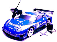
In this system, radio signals are not transmitted continuously but only generated when the controller sends a command to the left / right or forward / backward, and even then only a radio-frequency discontinuous, so is sending pulses of radio wave frequency.
The number of pulses sent represent commands sent, GO command is represented with 8 pulses, is represented with 16 pulses LEFT, RIGHT DOWN 32 pulses and 64 pulses. Commands that can dikirimk is a combination of 2 orders once gus, which is a combination of command forward / backward and right / left, for example, could be sent forward orders and left once gus, in this case the number of pulses sent is 24, ie the sum of the forward command by 8 pulse and left the command of 16 pulses.
After a command is sent, the system stops sending commands in a certain time lag, the lag time it takes will be a series of recipients have sufficient time to fulfilling their orders well. Frequency pulses were visible on the right side of this.
 |
| Radio Control Transmitter Series |
How it works Transmitter
Radio signals generated by oscillator circuit formed by transistors Q1 9016, the working frequency of the oscillator is determined by the crystal Y1 is worth 27.145 MHz. A very critical part of this oscillator circuit is T1, L1 and L2, which specifically dealt with separately at the end of this article. Working from this oscillator is controlled by NOR gate U2D 14001, while the output gate (pin 3) is worth 1, the oscillator will work and transmit radio frequency 27.145 MHz, and at the output U2D value 0 the oscillator will stop working. U2D NOR gate receives the clock signal from NOR gate U2B. NOR Gate CMOS type with the aid of resistors R4 and R5 and capacitor C8 form a low frequency oscillator circuit for controlling the clock shaper of existing digital circuits. Work of this clock generator is controlled via the input leg 6, the circuit will generate the clock if this input berlevel 0 .
NOR gate U2A and U2C form a series of Latch (RS Flip Flop), because of the influence of the resistor R2 and capacitor C11 is fed to pin 9 in U2C, when the circuit gets power supply output U2C must be 1 and the output of U2A (leg number 3) becomes 0 . This situation resulted Marja U2b clock generator works evoke reset the clock and remove the state of the enumerator 14 024 IC (U1), so that U1 started chopping and 27.145 MHz oscillator circuit sending pulses for generating a clock frequency of work.
At the start chopping, all the output of IC 14 024 enumerators in kedaan 0 , after chopping 8 Q4 output pulse (pin 6) will be a 1, after counting 16 pulses output Q5 (pin 5) to 1 , after chopping 32 Q6 output pulse (pin 4) to 1 , after counting 64 pulses output Q7 (pin 3) to 1.
Output over-output voltage used to control foot 9 U2C through diode D1 and D2, during one of the output is still worth 0 then the clock generator U2B still working, this will continue until the cathode D1 D2 dankatode be 1 so that the foot 9 U2C be a 1 as well. This situation will result in the output feet 3 U2A to 1 , which stop the clock generator U2B and resets the enumerator 14 024 danberhenti already shipping 27 145 MHz pulse frequency.
To generate the lag time for receiver circuit has enough time carrying out orders, used a series of Q2 9014, resistor R7 and capacitor C10. The amount of delay time is determined by the value of R7 and C10. Switch to send command forward / backward and to send commands left / right are two separate switches. Each switch has 3 positions, the center position means that the scalar does not send commands.
 |
| Radio Control Receiver series |
How it works Receiver
Figure 2 is a picture that matched the car receiver circuit toy, serves to receive signals from the transmitter to control motor cars, so cars can move forward / backward and left / right. Transistor Q1 with the help of resistors, capacitors and T1 form as a series of radio signal receiver 27.145 MHz. T1 in this series exactly the same as T1 that is used in the transmitter circuit, means of manufacture are discussed below.
Transistor Q2 follows perlangkapannya forming circuit to convert the radio frequency pulses received from the transmitter into the box pulses that can be accepted as a digital signal by the CMOS IC. Digital signal will be received as the clock had to be chopped by chopper 14 024 IC (U2). Output 14 024 will be in accordance with the number of pulses sent by the transmitter, forward command and left (which is used as an example in the discussion of the transmitter) is the pulse number of 24, the results of counting these pulses cause the output to be 14 024 Q4 = 1 , Q5 = 1, Q6 = 0 and Q7 = 0.
Digital signal received in addition be used as a clock IC 14 024 enumerators U2 discussed above, used also to drive the 3 pieces of the time delay circuit to generate pulses which controls the circuit work.
Toll regulator will first appear after delivery frequency pulse stopped because the lag time between sending the code, this pulse serves to record the count results to the U3 14 024 14 042 (D Flip Flop), making the final conditions of 14 024 will be retained to control the motor. After the results were recorded to 14 024 14 042, 14 042 enumerator is reset by the second pulse, after the lag time for 14,042 enumerators can count start from 0 again.
The circuit formed by transistors Q3, Q4, Q7, Q8, Q9 and Q10 named as H Bridge circuit, this circuit is very reliable to drive DC motors. With this series of DC motor can be rotated to the right-to-left or stop motion. The main requirement of the use of this circuit is the base voltage of Q7 and Q10 base voltage must be opposed, for example base Q7 = 1 and the base of Q10 = 0 the motor rotates to the left, the base of Q7 = 0 and the base of Q10 = 1 the motor will spin to the right, the base Q7 = 0 and the base Q10 = 0 motor stop motion, but it should not happen, the base Q7 = 1 and the base of Q10 = 1.
Similarly, Q5, Q6, Q11, Q12, Q13 and Q14 form a H Bridge. H Bridge to the left in Figure 2 is used to control motors that adjust the cars moving left / right, while the H Bridge right part is used to control motors that regulate movement forward / backward cars. The relationship between outpur enumerator 14 042 and 14 024 Input D Flip Flop is structured so that the signal is fed to each H Bridge can not be all 1 simultaneously.
Making transformer TX and RX
Transformer T1 in series transmitter and receiver, is the same stuff, and have created their own. Transformer was built using plastic transformer Koker (spare part radio) that have a step that looks 5 lanes that can be filled with rolls of wire, as shown in the photo. Using this Koker facilitate wire transformer winding. If you can not Koker similar to it, just use the usual. Koker feritnya transformer is small and is also small (3 mm) as the first is often used for assembly of 27 MHz CB radio.
Wire to the transformer can wear a wire in the unloading of these Koker, carefully open coil of wire that already exist within the Koker because the wire is smooth and quite easy to break.
Step 1: Roll away from the feet of wire fed into the number 5 ft 4 in the direction h (CW) as much as 3 rolls right in level 1 (point level above the lowest point)
Step 2: Wind the wire from leg 1 to leg 2 in a clockwise direction as much as 4 rolls right on level 2.
Step 3: Continue the roll (from step 2) clockwise a quarter roll to as much as 3 feet 3 at level three. (Can be determined exactly a quarter of the roll, because kokernya have a path cut into 4).
Making coil L1
Wind the copper wire diameter of 0.3 to 0.5 mm by 10 quarter rolls on Koker diameter about 4 mm (which will be released), also in a clockwise direction.
Making coil L2
Wind the copper wire diameter of 0.1 mm by 50 rolls of plastic Koker without ferrite diameter of about 3.5 - 4 mm (look for plastic materials from used goods) are also in a clockwise direction. The length of the section in liputi rolls along the 5 mm.
Subscribe to:
Posts (Atom)