Showing posts with label driver. Show all posts
Showing posts with label driver. Show all posts
Friday, November 22, 2013
Power supply with driver TEA1507
Power supply with driver TEA1507 is mostly used by TV branded PHILIPS. Power Supply has an efficiency rate of up to 90% - thus requiring less cooling, as well as stand-by power required is less than 1 watt.
Power Supply with TEA driver is equipped with a variety of surge protector that has a high reliability - not easily damaged if any part of a damaged power supply circuit and power transistor or FET heat is not easily damaged. Power supply circuits are dapatapat working on ac input voltage between 85 up to 275v. The way it works with the driver circuit power supply TEA 1507 is quite simple, so easy tracking of damage to the circuit.

The picture above is the basic power supply circuit with TEA1507

Wednesday, November 13, 2013
Bidirectional Motor Control Using L293 Driver
Using the L293 quadruple high-current half-H driver integrated circuit can be designed a very simple high efficiency motor control. The L293 is designed to provide bidirectional drive currents of up to 1 A at voltages from 4.5 V to 36 V. The L293D is designed to provide bidirectional drive currents of up to 600-mA at voltages from 4.5 V to 36 V.
Bidirectional Motor Control Circuit Diagram

Each output is a complete totem-pole drive circuit, with a Darlington transistor sink and a pseudo-Darlington source. Drivers are enabled in pairs, with drivers 1 and 2 enabled by 1,2EN and drivers 3 and 4 enabled by 3,4EN. When an enable input is high, the associated drivers are enabled and their outputs are active and in phase with their inputs. When the enable input is low, those drivers are disabled and their outputs are off and in the high-impedance state. With the proper data inputs, each pair of drivers forms a full-H (or bridge) reversible drive suitable for solenoid or motor applications.
External high-speed output clamp diodes should be used for inductive transient suppression. In this bidirectional stepper motor controller electronic project VCC1 is logic supply and must me between 4.5 and 7 volts ( typically 5 volt) and VCC2 is the power supply for the motor and must be from VCC1 up to 36 volts.
Bidirectional Motor Control Circuit Diagram
Each output is a complete totem-pole drive circuit, with a Darlington transistor sink and a pseudo-Darlington source. Drivers are enabled in pairs, with drivers 1 and 2 enabled by 1,2EN and drivers 3 and 4 enabled by 3,4EN. When an enable input is high, the associated drivers are enabled and their outputs are active and in phase with their inputs. When the enable input is low, those drivers are disabled and their outputs are off and in the high-impedance state. With the proper data inputs, each pair of drivers forms a full-H (or bridge) reversible drive suitable for solenoid or motor applications.
External high-speed output clamp diodes should be used for inductive transient suppression. In this bidirectional stepper motor controller electronic project VCC1 is logic supply and must me between 4.5 and 7 volts ( typically 5 volt) and VCC2 is the power supply for the motor and must be from VCC1 up to 36 volts.
Sunday, October 20, 2013
Loudspeaker Driver Circuit
The series of loudspeaker drivers are electronic circuits that function to bridge between high-output circuit with a loudspeaker berimpedasi berimpedansi low.

Why this driver is needed so that the output voltage to be inserted into the loudspeaker is not impaired. Declining value of this voltage is very possible given the lack of rules regarding the distribution of voltage and resistance instead of parallel. Where every prisoner that is placed parallel with other prisoners or the inmates totally substitute for detainee custody is smaller than with individual prisoners themselves. For example, 10 ohm resistance 10 ohms paralleled with the prisoners would get custody instead of 5 ohms. Resistivity 10 ohm to 100,000 ohm paralleled the total resistance is 9.9990 ohms. So it can be concluded that the total voltage will always be smaller than the origin of each detainee. Then, with a decrease in resistance (only using a combination of resistors) or the impedance of the output terminals before, then in accordance with the laws of the voltage divider in series can be ascertained that the prisoners connect in series with output terminal will have a larger part of the voltage and output terminal itself will decline voltage.
The working principle speaker driver circuit is actually very simple and easy to understand. Where the input signal is only used as a trigger to move the second driver transistor to the rhythm of the input signal. While the current that would flow to the loudspeaker most of the power supply driver circuit. You could say similar to the use of transistors as switches. Therefore, in this speaker series driver not found a combination of resistors for reinforcement. So if we look at the picture above, so most of the current flowing in the loudspeaker load is derived from the 9 volt supply voltage, instead of the input ac signal, so that the input signal will not be burdened.
Thursday, October 17, 2013
Motor driver L298 Circuit
DC motor driver with H-Bridge IC L293D
IC H Bridge DC motor driver L298 has two H-Bridge circuit in it, so it can be used to download the drive two DC motors. H Bridge DC motor driver L298 each can deliver currents up to 2A. However, in use, the H Bridge DC motor driver L298 can be used in parallel, so the ability to deliver the H Bridge DC motor driver L298 flow into 4A. The consequences of the installation of H Bridge L298 DC motor driver with the parallel mode, you need 2 pieces Bridge H L298 DC motor driver to control two DC motors using H bridge DC motor driver L298 in parallel mode.
H Bridge Pin IC L298 DC motor driver which is connected in parallel operation mode:* OUT1 connected to OUT4.
* OUT2 OUT3 linked.
* IN1 is connected to IN4.
* IN2 connected to IN3.
* ENABLE ENABLE A linked to B.

OUT1/OUT4 and OUT2/OUT3 associated with DC motors to be controlled.
Please note that the output of the L298 does not have a safety diode. Thus, the need to add two diodes - flyback diodes, with appropriate current capability, at any point output.
Monday, September 16, 2013
6 Channel LED Driver Using MCP34845
A very simple 6 channel low cost led driver electronic circuit project can be designed using the MCP34845 LED drivers manufactured by Free scale Semiconductor.The MCP34845 LED drivers operates from 5 to 21 volts and is specially designed for use in back lighting LCD displays from 10" to 17"+ for devices like : PC Notebooks , Net books , Picture Frames , Portable DVD Players , Small Screen Televisions , Industrial Displays , Medical Displays , etc.
6 Channel LED Driver Circuit Diagram
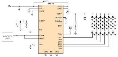
The MCP34845 LED drivers is capable of driving up to 16 LEDs in series in 6 separate strings.PWM dimming is performed by applying a PWM input signal to the PWM pin which modulates the LED channels directly.Main features of this driver circuit project are : input voltage of 5.0 to 21 V , boost output voltage up to 60 V, 2.0 A integrated boost FET , fixed boost frequency - 600 kHz or 1.2 MHz , OTP, OCP, UVLO fault detection , LED short/open protection , programmable LED current between 3.0 mA and 30 mA .
6 Channel LED Driver Circuit Diagram
The MCP34845 LED drivers is capable of driving up to 16 LEDs in series in 6 separate strings.PWM dimming is performed by applying a PWM input signal to the PWM pin which modulates the LED channels directly.Main features of this driver circuit project are : input voltage of 5.0 to 21 V , boost output voltage up to 60 V, 2.0 A integrated boost FET , fixed boost frequency - 600 kHz or 1.2 MHz , OTP, OCP, UVLO fault detection , LED short/open protection , programmable LED current between 3.0 mA and 30 mA .
Subscribe to:
Posts (Atom)