Showing posts with label 3. Show all posts
Showing posts with label 3. Show all posts
Thursday, November 14, 2013
Regulated Dual 3 Watt White LED Lamp
This project involves constructing an energy efficient dual 3 Watt white LED array that runs on 12VDC at 700mA. The lamp is useful for indoor indirect room lighting. The light that is produced does not flicker and has a regulated brightness from 11V to the maximum operating voltage. The Avago 3W white LEDs are rated at 3 watts (nominal). Never stare directly at this lamp when it is running at full operating power, it is dangerously bright.

Specifications:
The lamp is wired as a current loop which includes the power supply, the LED series string and the 700 mA current regulator circuit. The LM317 and 1.8 ohm 5 Watt resistor act as a current regulator that limits the loop current to 700 mA. Two 100nF monoblock capacitors bypasses the LM317 IC.
Construction:
The LEDs and current regulator circuit were mounted on a 3" x 6" piece of blank double-sided circuit board stock. The two LEDs and the LM317 regulator were soldered directly to the circuit board copper using a 200/240W soldering gun. The circuit board should be pre-tinned with solder and soldering should be done quickly to avoid overheating the parts.
The Avago LEDs come in several variations, the part used has an electrically isolated mounting tab, this feature is necessary for preventing a short circuit. If you cant find an LED with an isolated tab, be sure to mount each LED on its own isolated copper board. As of 2012, the specified LEDs are no longer available but there are plenty of other 700mA,3.7V white LEDs available. Just be sure to select one that you can easily solder to and connect to a heat sink.
The first version of this prototype ran too hot, so an aluminum heat sink was bolted to the board near the voltage regulator. Soldering the LM317 tab directly to the circuit board makes the board electrically hot at 1.8V, the board should not be allowed to come into contact with any live conductors. The LM317 may be optionally mounted on an insulated spacer to electrically isolate the board, in this arrangement, a TO-220 heat sink should be directly attached to the LM317.
The two resistors shown in the photo are combined in parallel to make a 1.8 ohm resistance, a single part would be a better choice. The entire circuit board can be mounted inside of a piece of aluminum "U" channel using plastic spacers for electrical isolation. The "U" channel reflects the bright light away from the side.
Use:
Connect this circuit to a 12VDC power supply or other power source such as a solar-charged lead acid battery. Be sure to observe the correct polarity. Look away from the LEDs and apply power. Again, do not stare directly at the LEDs. Prolonged exposure may harm your vision. A switch-mode power supply rated at 12VDC and 1 Amp or more is the most energy-efficient way to power one of these devices from line power. Your author liked this lamp so much that he constructed three of them to run in parallel and light his main electronics work bench.
Parts:
1x LM317 TO-220 case 1A adjustable voltage regulator
1x 1.8 ohm 5W resistor
2x 100nF 35V or higher monolythic capacitor
2x Avago ASMT-MYE2-NMN00 isolated tab 700mA,3.7V warm white LED or equivalent
3"x6" piece of double-sided copper circuit board stock
Miscellaneous wire, solder lugs, termination strips and hardware,
Large aluminum mounting plate, heat sinks if necessary.
Specifications:
- Nominal operating voltage: 12V DC
- Nominal operating current: 700 mA
- Maximum operating voltage: 16V DC
- Power consumption at 12.0V: 8.4W
- Minimum voltage for regulated light: 11V DC
- Leds produce light down to: 6V DC
- White LED voltage: 3.7V DC each
- White LED input power: 2.59 W each
- Voltage across regulator when current becomes regulated: 3.3V DC
The lamp is wired as a current loop which includes the power supply, the LED series string and the 700 mA current regulator circuit. The LM317 and 1.8 ohm 5 Watt resistor act as a current regulator that limits the loop current to 700 mA. Two 100nF monoblock capacitors bypasses the LM317 IC.
Construction:
The LEDs and current regulator circuit were mounted on a 3" x 6" piece of blank double-sided circuit board stock. The two LEDs and the LM317 regulator were soldered directly to the circuit board copper using a 200/240W soldering gun. The circuit board should be pre-tinned with solder and soldering should be done quickly to avoid overheating the parts.
The Avago LEDs come in several variations, the part used has an electrically isolated mounting tab, this feature is necessary for preventing a short circuit. If you cant find an LED with an isolated tab, be sure to mount each LED on its own isolated copper board. As of 2012, the specified LEDs are no longer available but there are plenty of other 700mA,3.7V white LEDs available. Just be sure to select one that you can easily solder to and connect to a heat sink.
The first version of this prototype ran too hot, so an aluminum heat sink was bolted to the board near the voltage regulator. Soldering the LM317 tab directly to the circuit board makes the board electrically hot at 1.8V, the board should not be allowed to come into contact with any live conductors. The LM317 may be optionally mounted on an insulated spacer to electrically isolate the board, in this arrangement, a TO-220 heat sink should be directly attached to the LM317.
The two resistors shown in the photo are combined in parallel to make a 1.8 ohm resistance, a single part would be a better choice. The entire circuit board can be mounted inside of a piece of aluminum "U" channel using plastic spacers for electrical isolation. The "U" channel reflects the bright light away from the side.
Use:
Connect this circuit to a 12VDC power supply or other power source such as a solar-charged lead acid battery. Be sure to observe the correct polarity. Look away from the LEDs and apply power. Again, do not stare directly at the LEDs. Prolonged exposure may harm your vision. A switch-mode power supply rated at 12VDC and 1 Amp or more is the most energy-efficient way to power one of these devices from line power. Your author liked this lamp so much that he constructed three of them to run in parallel and light his main electronics work bench.
Parts:
1x LM317 TO-220 case 1A adjustable voltage regulator
1x 1.8 ohm 5W resistor
2x 100nF 35V or higher monolythic capacitor
2x Avago ASMT-MYE2-NMN00 isolated tab 700mA,3.7V warm white LED or equivalent
3"x6" piece of double-sided copper circuit board stock
Miscellaneous wire, solder lugs, termination strips and hardware,
Large aluminum mounting plate, heat sinks if necessary.

Simple 3 Transistor Amplifier
Mini 3 transistor amplifier is a simple amplifier with 50mW power drawn by 3 transitor. The series of three mini-amplifier transistors can be used for loud speaker 8 ohm load. Source voltage required to activate the mini-amplifier can be drawn from the batteries 9V.Rangkaian 3 transistor amplifier is often used in simple portabe audio devices such as radios or small tape recorder. Mini-transistor amplifier circuit 3 is quite simple as shown in the figure below.

Mini-transistor amplifier circuit 3 includes type of amplifier OTL (Output Transformer Less). Mini-transistor amplifier circuit 3 is used for output coupling capacitors. Amplifier circuit is simple and suitable when used for audio amplifier experiment.
[Continue Reading]
Mini-transistor amplifier circuit 3 includes type of amplifier OTL (Output Transformer Less). Mini-transistor amplifier circuit 3 is used for output coupling capacitors. Amplifier circuit is simple and suitable when used for audio amplifier experiment.
3 Level Audio Power Indicator

This circuit is designed to indicate the power level output of any audio amplifier. Its simple, portable, and displays three power levels can be adjusted to any desired value. For a standard power amplifier hi-fi stereo, the output values suggested are:
- D5 illuminates at 2W
- D4 illuminates at 12.5W
- D3 illuminates at 24.5W
Tuesday, November 5, 2013
3 Volt Car Adapter
The The Schematic of 3 volt Car Adapter was posted by taking part in type Car. Please examine suspiciously and realize on schematic design pictures of The Schematic of 3 volt Car Adapter to find specify in order.
 |
| 3 volt Car Adapter Schematics |
This 3 volts Car Device journey is based on a provide LT1074CT switching control IC. The schematic shows the LT1074CT misused equally a affirmatory step-down before ‘buck’ convertor. The ’switcher’ is old to trade a +12-volt car barrage emf consume to +3 volts pro make use of with the personalised goodbye-fi’s and handheld games for the author’s two boisterous children on sesquipedalian car journeys. State on under ten time of age, children offer rarely remain see you later-fi admirer’s and are mostly not caring with at all disturbance generated by the ’switcher ‘circuit.
The journeying is coupled to the car +12-vs. order via the smoke lighter socket - is rational to use a compound edition of the fag light stopple. The +12-against arrives on the relations via screw- pole impede J2. Diode D2 provides a verso emf indorsement, scrap C3 decouples the input to the switcher IC.
Saturday, October 26, 2013
3 Band Tone Control with LF351
3 Band Tone Control circuit uses an op-amp as an amplifier end. Tone Control circuit is a regulator of tone bass, midrange and treble or 3 band called because it can set the three tones. Filter circuit is applied to the series of "Tone Control 3 band" This type baxandal like the title of this article.
Results filtering regulator tone or tone control baxandal type is good, because there is no signal level is wasted directly into the ground. Range frequency tones generated from Tone Control 3 band was determined by the configuration of the R and C of the filter section baxandal. As an amplifier on Tone Control The set of three band use traditional IC LF351 has slewrate high and high input impedance. For more details, series 3 Band Tone Control as follows.
Figure Series 3 Band Tone Control

3 Band Tone Control circuit above using LF351 Op-Amp is used to strengthen the signal after filtering by the filter process baxandal. Level tone Bass, Midrange and Treble settings are determined by potensio R1, R2 and R3. Frequency filter in the circuit above baxandal to 50 Hz bass tone, tone Midrange 1 KHz and 10 KHz for Treble tone.
Sunday, October 20, 2013
2 x 2 3 Watts power amplifier schematics
Do not misunderstand, this series is one of several series of power amplifiers that have output / low output power. This amplifier output is only possess more or less 4Watt. Or 2 X 2Watt stereo power amplifier. Minimum required voltage is not less than 3 volts and a maximum voltage of no more than 14 volts, and voltage must be rectified and filtered to obtain the maximum of the processed audio.

Component List :
R1 = 2,7R
R2 = 2,7R
C1 = 1uF
C2 = 1uF
C3 = 100uF
C4 = 220uF
C5 = 100uF
C6 = 100uF
C7 = 220uF
C8 = 0.1uF
C9 = 0.1uF
C9 = 0.1uF
C10 = 470uF
C11 = 470uF
U1 = ULN3750B
Wednesday, October 2, 2013
3 channel audio mixer
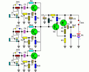
3 channel audio mixer is built using some of the transistor amplifier.
3 channel audio mixer circuit uses voltage 9VDC summber which can supplied from a battery. 3 channel audio mixer circuit is designed special for the purposes of this Public Amplifier.
Because the audio circuit of this mixer is designed specifically for the purpose of a portable mixer for audio public then this series has only a volume control without the tone control. Image series that looks below audio mixer is a series of mono, if you want to make a 3 channel stereo audio mixer it is necessary to make 2 pieces of a series of three channel audio mixer terebut. For more details, a series of three channel audio mixer can be seen in the following image.
3 channel audio mixer circuit uses voltage 9VDC summber which can supplied from a battery. 3 channel audio mixer circuit is designed special for the purposes of this Public Amplifier.
Because the audio circuit of this mixer is designed specifically for the purpose of a portable mixer for audio public then this series has only a volume control without the tone control. Image series that looks below audio mixer is a series of mono, if you want to make a 3 channel stereo audio mixer it is necessary to make 2 pieces of a series of three channel audio mixer terebut. For more details, a series of three channel audio mixer can be seen in the following image.
 |
| 3 channel audio mixer circuit |
Sign Component Audio Mixer With 3 Chanel Transistor
P1, P2, P3 = 5K
R1, R11, R15 = 180K
R2, R12, R16 = 2M2
R3, R13, R17 = 750R
R4, R14, R18 = 1K
R5 = 15K
R6 = 220R
R7 = 1.5K
R8 = 820R
R9 = 150R
R10 = 100K
C1, C6, C8 = 1μF-63V
C2, C4, C7, C9 = 100μF-25V
C3, C5 = 220μF-25V
Q1, Q4, Q5 = BC550C
Q2 = BC547 should
Q3 = BC557
J1, J2, J3 = 3mm Mono sockets
SW1, 2,3,4 = SPST Toggle
In a series of three channel audio mixer is equipped with a switch on each chanelnya which select the input impedance, when the switch SW1, SW2 and SW3 in the open then the input should come from the output signal with a high level such as VCD, MP3 player, tape, computer and tuner . And at SW1, SW2 and SW3 closed position, the input should come from a weak audio signals such as microphones.
Saturday, September 28, 2013
3 4 W power amplifier schematic
The schematic above is amplifier based on ic TA7211P or TA7212P , circuit above using OT transformer as a booster amplifier again. The amplifier suitable used on outside / field, because by using a transformer OT is identical to the PA amplifier.

Part List :R = 1K , 10R , 3K3C = 1uF , 10uF , 1n , 68u, 3u3, 2n2 x 2, 100uIC = TA 7211P / TA7212PTechnical information :Max Vcc = 15 VDCMin Vcc = 4 VDCPo = 3,4 WRl = 8 OhmIcco = 16 mA
Saturday, September 21, 2013
Mini Amplifier with 3 Transistor
Mini 3 transistor amplifier is a simple amplifier with 50mW power drawn by 3 transitor.
The series of three mini-amplifier transistors can be used for loud speaker 8 ohm load. Source voltage required to activate the mini-amplifier can be drawn from the batteries 9V.Rangkaian 3 transistor amplifier is often used in simple portabe audio devices such as radios or small tape recorder. Mini-transistor amplifier circuit 3 is quite simple as shown in the figure below.
Mini-transistor amplifier circuit 3 includes type of amplifier OTL (Output Transformer Less). Mini-transistor amplifier circuit 3 is used for output coupling capacitors. Amplifier circuit is simple and suitable when used for audio amplifier experiment.
[Continue Reading]
The series of three mini-amplifier transistors can be used for loud speaker 8 ohm load. Source voltage required to activate the mini-amplifier can be drawn from the batteries 9V.Rangkaian 3 transistor amplifier is often used in simple portabe audio devices such as radios or small tape recorder. Mini-transistor amplifier circuit 3 is quite simple as shown in the figure below.
Mini-transistor amplifier circuit 3 includes type of amplifier OTL (Output Transformer Less). Mini-transistor amplifier circuit 3 is used for output coupling capacitors. Amplifier circuit is simple and suitable when used for audio amplifier experiment.
Monday, September 16, 2013
BTL Stereo Amplifier TDA7052 3
This is BTL stereo power amplifier with basic amplifier on IC TDA7052 / TDA7053

[Continue Reading]
Subscribe to:
Posts (Atom)