Thursday, October 31, 2013
Ionization Smoke Detector Using A5367
This detector needs to be powered by a 9 volts DC power supply (or a 9 volts battery ) .Circuit require few external components and is very easy to be configured . As you can see in this diagram , the sound alarm is “produced “ by an piezoelectric element .
Ionization Smoke Detector Circuit Diagram

An internal timer is provided that can be used in various configurations to allow a period of reduced smoke detector sensitivity, referred to as Timer (or Hush) mode. Internal test circuitry allows low battery check by holding the FEEDBACK and OSC CAP pins low during power-up, then reducing VDD and monitoring the HORN1 pin
Line Following Robot Sensor
IC1 contains an infrared LED and a phototransistor. The LED emit invisible infrared light on the track and the phototransistor works as a receiver. Usually, black colored surface reflects less light than white surface and more current will flow through the phototransistor when it is above a white surface. When a reflection is detected (IR light falls on the phototransistor) a current flows through R2 to ground which generates a voltage drop at the base of T1 to make it conduct. As a result, transistor T2 start conducting and the visual indicator LED(D1) lights up. Capacitor C2 works as a mini buffer.
Line Follower Robot Scanner Circuit diagram:

The red color LED (D1) is only a visual indicator. You can add a suitable (5V) reed relay in parallel with D1-R4 wiring after suitable alterations to brake/stop/redirect the robot. Similarly, the High to low (H-L) transition at the collector of T2 can be used as a signal to control the logic blocks of the robot. Resistor R1 determines the operating current of the IRLED inside IC1. The sensing ability largely depends on the reflective properties of the markings on the track and the strength of the light output from IC1.
Simple USB player circuit with PCM2902

In this usb circuit using an IC as a modifier of digital voice data into analog so that it can be applied to a headphone, or again through the power amlplifier strengthened so that it can be heard through the speakers. IC used in this circuit using IC PCM2902 as a modifier of a digital data into analog data storage.
 |
| Schematic usb player |
Simple USB player circuit with PCM2902

In this usb circuit using an IC as a modifier of digital voice data into analog so that it can be applied to a headphone, or again through the power amlplifier strengthened so that it can be heard through the speakers. IC used in this circuit using IC PCM2902 as a modifier of a digital data into analog data storage.
 |
| Schematic usb player |
Wednesday, October 30, 2013
Digital tone control with MAX5406
The series will I make here is a series regulator of Volume, Bass, and Balance Trable Digital (Tone Control). The core of this circuit is an IC-type output from the Manufacturer Maxim MAX5406, while the IC is an audio processor that comes with the interface switch hit for Tone Control setting above. The circuit scheme is as follows:
The scheme above uses very little supporting components and this makes can be made with a mini size of a matchbox only even if using all SMD components can be reduced in size by half for this time I will only give a simple layout made, following picture:

 |
| layout components |
Simple Source Voltage Protector

Source voltage surge protector will expressed in this article are general, so that later in their applications to stay adjusted value of the component with the voltage source needs an electronic appliance. Let us start reviewing Protectors Voltage Source by simple and modest.
 |
| Source voltage protection with 1 diode |
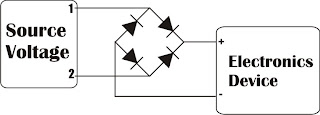 |
| Source voltage protection with dioda bridge |
Police Sirine Circuit with IC 555

Tuesday, October 29, 2013
High End Power Amplifier Wiring Circuit

20 Watt Schematics power amplifier
This circuit is mono amplifier use IC TDA1010A .Minimum voltage require 4V and maximum voltage 24V. To avoid damaged IC please use supply voltage 12 volt and must be filtering voltage. Power output 20 W with impedance 4 Ohm. IC equation with : TDA1011, TDA1011A , TDA1015 , and TDA1020.
See circuit schematic and troubleshooting amplifier :

If circuit circuit above not working , errors may occur in :
- Supply Voltage.
- Damaged Component , such as : IC , resistor or capcitor.
- Input output cable not connected.
- Damaged speaker.
- Short-circuit input with ground.
- Tuner
- Pream Head / Tape
- Mic
- CD or DVD player
- PC
- MP4 player
- etc.
2 X 0 32W BA5386 amplifier schematic
Amplifier circuit above scheme is a combination of the two IC was then made into one of its supply voltage so it does not require a lot of supply voltage and output a stereo input. Output issued also very low at 2 X 0.32 W and has 8 ohm impedance. Indeed, this amplifier has a very low output, but the amplifier is quite easy to make and does not require much cost. The voltage required at least 4 volts while the maximum supply voltage of 12 volts.

R1,R2______50K trim
C1,C2______3u3F
C3,C4______100uF
C5,C6______470uF
U1,U2______BA5386
FPF270X Over Current Protection

All devices clamp the load current so that it cannot exceed an externally programmed current level. An over temperature feature provides further device protection in case of excessive levels of power dissipation.
FPF2700 responds to an overload condition that lasts longer than a fixed blanking period by turning off the load, followed by a retry after the auto-restart time.The FPF270X has an adjustable 0.4A to 2.0A minimum current limit set through an external resistor, RSET, connected between ISET and GND.A 4.7 F to 100 F ceramic capacitor is adequate for CIN in most cases. Larger CIN values may be required in high-voltage or high-current applications.

A 0.1 F to 1 F capacitor, COUT, should be placed between the OUT and GND pins. This capacitor helps prevent parasitic board inductances from forcing the output voltage below ground when the switch turns off.
During a hard short condition on the output while operating at greater than 24V VIN, a large instantaneous inrush current is delivered to the shorted output. A capacitor must be placed at the OUTPUT pin, acting as a current source to support the instantaneous current draw (Table 2).

For more details about how to design a protection circuit using FPF270X IC please consult the manufacturer datasheet.
Monday, October 28, 2013
Essential Home Theater Design
 Relations every time require to bring habitat particular luxurious home entertainment structure. This is for the reason that just very a small number of households can afford home drama system. Of tardy, only the rich and the famous can afford such luxury. This notion is right away a feature of the ancient history. Home plays systems may well now stay vacant to greater numeral of households since of the familiarity of principal home drama design. The basic home theater design may well just require three basic components and these three components might already take place within your means in lieu of the working course group.
This is for the reason that even for the home acting design, you might need to consider the sight and sound of a picture drama. It is the chief consideration why dwell in stab to a show drama, the immense screen and the surround sound. With respect to the surround sound of a picture plays, the major three speakers is barely applicable on behalf of lesser quarters, if the space is larger, the local the stage design needs to take place added than three, you may perhaps go up to six speakers and a complimenting subwoofer may be needed for the surround effect. leaving back to a trivial space, if you force lone locate three speakers, you may perhaps care for to consider export a tall quality brand loudspeaker; this will make happen you adequate surround sound on behalf of a less significant scope.
Guitar Control Circuit Diagram
 Guitar Control Circuit Diagram
Device purpose:
This preamplifier was advised as a stand-alone carriageable unit, advantageous to ascendancy the signals generated by guitar pick-ups, decidedly the acquaintance "bug" types activated to acoustic instruments. Obviously it can be acclimated with any blazon of apparatus and pick-up.
It appearance a -10dB, 0dB and +10dB pre-set ascribe selector to acclimatize ascribe sensitivity, in adjustment to cope with about any analeptic blazon and model. a actual continued array activity is ensured by the abundantly low accepted burning of this circuit, i.e. beneath than 800µA.
Circuit operation:
IC1A op-amp is alive as an inverting amplifier, accepting its accretion set by a three means about-face inserting altered amount resistors in alongside to R4. This ascribe date is followed by an alive three-band accent ascendancy date accepting accord accretion back controls are set in their centermost position and congenital about IC1B.
Melody Generator using M66T
 Melody Generator using M66T
Components List:
C = 1uF
R = 4.7KW
Q = 2SC9013
About IC M66T series:
The M66T series is a CMOS LSI designed melody generator IC for use in telephones and toys application. It has an on-chip ROM programmed for musical performance. Produced by CMOS technology, the device results in very low power consumption. And with built-in RC oscillator, a compact melody module can be constructed with only a few additional components.

- Pin 1 (O/P) Melody Output
- Pin 2 (Vdd) Positive Power Supply
- Pin 3 (Vss) Negative Power Supply
The following are the M66T series and the song generated by its series:
- M66T-01L : Jingle Bells + Santa Claus Is Coming To Town + We Wish You A Merry Christmas
- M66T-05L : Home Sweet Home
- M66T-09L : Wedding March (Mendelssohn)
- M66T-19L : For Alice
- M66T-68L : It Is A Small World
Sunday, October 27, 2013
Direction Sensor CMPS03

Magnetic Compass Module Functions in the contest CMPS03 usually to provide a reference where the robots are in position and lead anywhere, then the position and direction provided by the Magnetic Compass Module reference sebgai CMPS03 the next robot motion. Magnetic Compass Module uses I2C data communication lines to mirokontroler. With adalanya I2C data communication lines from this CMPS03 this module can be connected directly to a microcontroller that suport with I2C data communication channels such as AVR ATMega. Magnetic Compass Module CMPS03 require 5 V voltage with 15mA current.
 |
| CMPS03 Circuit Diagram |
Because the module using I2C Magnetic Compass CMPS03 we can use 5 lines are:
VCC + 5 V on pin 1
SCL with Pull Up resistor 10 K
SDA with Pull Up resistor 10 K
Calibrate the PIN associated with micro switch 6
Ground on PIN9
Subwoofer Filter and Low Pass Filter with LM741
Subwoofer Filter and Low Pass Filter Circuit Diagram

The low Summary of the amplifier signals go to a second low-pass filter to prevent the frequency from the speakers. I decided, a second order, as this box with a closed place feature. If you have a circuit with a valve system, and then simply close the Wind (Roll a pair of socks and pick at the port / Wind), this will give you a sealed box instead.
0 15Watt amplifier schematic

Amplifier circuit is also very suitable when used in fm radio receiver. Supply voltage required 8 - 25 Volt DC with a maximum output power 0.15W.See Schematic below.Part List
R1 = 100R
C1 = 1nF
C2 = 4.7uF
C3 = 10uF
C4 = 100uF
C5 = 47uF
C6 = 4.7nF
U1 = TA7066
32 768 KHz Oscillator using Watch Crystal
 32.768 KHz Oscillator using Watch Crystal
a 32.768 KHz square wave from a common watch crystal. The output can be fed to a 15 stage binary counter to obtain a 1 second square wave. The circuit on the left using the 4069 inverter is recommended over the transistor circuit and produces a better waveform. The single transistor circuit produces more of a ramping waveform but the output swings the full supply voltage range so it will easily drive the input to a CMOS binary counter.
Saturday, October 26, 2013
RS232 to RS485 Circuit
 |
| Click image to view larger RS232 to RS485 Circuit |
3 Band Tone Control with LF351
Figure Series 3 Band Tone Control

Crystal Radio Audio Amplifier Circuit
 Crystal Radio Audio Amplifier Circuit
The TL431 is accessible in a TO-92 amalgamation and it looks like an accustomed transistor so your hobbyist accompany will be afflicted by the aggregate you are accepting with alone one transistor! The amplifier may be acclimated for added projects, too. Higher impedance headphones and speakers may additionally be used. An earphone from an old blast will accord boisterous aggregate and abundant sensitivity! The 68 ohm resistor may be added to several hundred ohms back application aerial impedance earphones to save array power.
Stepper Motor Controller Using by A3952S
A3952S Stepper Motor Controller Circuit diagram

As you can see in the schematic diagram , this stepper motor driver circuit require two A3952S circuits and other few additional electronic components.
Friday, October 25, 2013
Self Installation of Auto Sound System can Save Serious Cash
Emergency Light Flashlight
When its used having the status of a nightlight it is a not much dimmer but still upbeat adequate to perceive your way around.
The light stays on a bunch longer than the circular emergency plug concerning illumination with the aim of Ive used in the older and it looks a lot better than them. I carry out think it would look even better devoid of the flashlight part of the light and I would have a preference to grasp a version like with the aim of if theyd offer it.
Once plugging into a lookalike outlet it still leaves area intended for a lesser plug to progress into the outlet then to it.
Simple But Reliable Car Battery Tester
This solution is better than letting the internal voltage regulator set the 12V sample voltage to be feed into the internal voltage divider simply because it cannot regulate 12V when the voltage drops lower (linear regulators only step down). Simply wiring with no adjust, the regulator provides stable 1,25V which is fed into the precision internal resistor cascade to generate sample voltages for the internal comparators. Anyway the default setting let you to measure voltages between 8 and 12V but you can measure even from 0V to 12V setting the offset trimmer to 0 (but i think that under 9 volt your car would not start).
Car Battery Tester Circuit diagram:

There is a smoothing capacitor (4700uF 16V) it is used to adsorb EMF noise produced from the ignition coil if you are measuring the battery during the engine working. Diesel engines would not need it, but Im not sure. If you like more a point graph rather than a bar graph simply disconnect pin 9 on the IC (MODE) from power. The calculations are simple (default)
For the first comparator the voltage is : 0,833 V corresponding to 8 V
* * * * * voltage is : 0,875 V corresponding to 8,4 V
for the last comparator the voltage is : 1,25 V corresponding to 12 V
Have fun, learn and dont let you car battery discharge... ;-)
e-mail: jonathan.filippi@virgilio.it
Thursday, October 24, 2013
Alpine Audio Amplifier 500 Watt RMS
MRP-M500 - Alpine Monoblock 500 Watt RMS Power Amplifier :
Product Features
- Mono subwoofer car amplifier
- 300 watts RMS x 1 at 4 ohms (500 watts RMS x 1 at 2 ohms)
- Class D amp with MOSFET power supply
- 10-11/16"W x 2-7/16"H x 9-9/16"D
Technical Details
- Brand Name: Alpine
- Model: MRP-M500
- Faceplate Type: Detachable
- Device Type: Amplifier
- MP3 player: N
- Warranty: 1 year warranty
Isobaric loading Subwoofer Box

Wednesday, October 23, 2013
LM2901 LED bar graph meter
Several LED above and other components used to determine the signal amplifier, when in a state of high and low . If the signal received from the amplifier circuit is high then the LED lamp are lit up everything and more bright LED lamps, but otherwise if the received signal is low then the lights on only one or two , even absent or faint.
To use the circuit you can connec with the output amplifier or speaker output , if there is reinforcing the other in the amplifier , can be connected to the output.

Mini Subwoofer 5 6 Bandpass 4th Order Isobaric
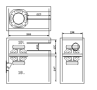 |
| Mini Subwoofer 5 -6" Bandpass 4th Order Isobaric |
- Nominal Basket Diameter 5 "/ 125mm
- Impedance 8 ohm
- RMS Power 50 Watts
- Program Power 100 Watts
- Frequency response 50Hz - 12.0kHz
- Sensitivity (1W/1m) 91dB
- Voice Coil Diameter 1 "/ 25.8mm
- BL Factor 6.4 N / A
- Voice Coil Length 14 mm
- Air Gap Height 6mm
- X Damage (peak to peak) 20 mm
- Magnetic Assembly Weight 2.2 lbs / 1.0 kg.
- Edit Information
- Diameter 5.28 "/ 134mm x 5.28" / 134mm
- Bolt Circle Diameter 5.4 "/ 137mm
- Baffle Cutout Diameter --
- - Front Mount 4.72 "/ 120mm
- Many of the 4 mounting holes
- Volume displaced by driver, 019 m 3 / .5 liter
- Total Depth 2.68 "/ 68mm
- Net weight 2.64 lbs / 1.2 kg.
- Weight 2.8 lbs / 1.27 kg.
- Materials
- Basketball aluminum diecast
- Polypropylene cone
- Rubber Surround
- Voice Coil Wire Copper
- Ferrite
- Thiele-Small Parameters
- Resonance Frequency (FS) 60 Hz
- Impedance (Re) 5.33 ohms
- Coil Inductance (Le) 0.4 mH
- Mechanical Q (Qms) 1.604
- Electrical Factor (Qes) .35
- Total Q (Qts) .29
- Comp. Equivalent Vol. (Vas) 35 FT3 / 9.8 Liter
- Voice Coil Overhang (Xmax) 4.0mm
- Reference yield 5%
- Volume Displacement 34 cm3
Class A headphone amplifier
 |
| Class A headphone amplifier |
Tuesday, October 22, 2013
Auto Alarm Schematic
During the time delay, half of LED1, which is actually a single, bi-colored, three-legged common cathode device, lights green. At the same time, pins 8 and 4 of U2 (a 555 oscillator/timer) are held low by Ul (a 3905 oscillator/timer), causing the alarm to remain silent. Once the delay is over, LED1 turns red, indicating that the circuit is armed.
Auto Alarm Schematic Circuit Diagram

Diode D1 ensures that the green segment of LED1 is fully extinguished when Ql is turned on-which turns the LED to red. Resistors R4 and R5 must be connected to the + V bus. not to pin 7 of Ul. otherwise U2 will mysteriously trigger itself each time the initial delay ends.
Preamplifier Circuit Diagram DCF77
 |
| DCF77 Preamplifier Circuit Diagram |
The pair of transistors power amplifier

Vertical IC Configuration
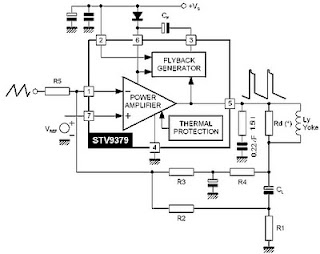 |
| Vertical IC Configuration AC Coupling |
 |
| Vertical IC Configuration DC Coupling |
Monday, October 21, 2013
High voltage inverter circuit diagram

This inverter circuit works with a transistor and transformer and other components to increase the voltage becomes high. Input supply voltage ranging from 3V to 6V DC, later it was raised to high voltage AC. However, in this inverter circuit output current is very small, probably under 0.1A even smaller. However, its use you can apply it on a fluorescent lamp 10W maximum power only, and that too takes time to switch on fluorescent lamps.Part List
R1 = 4K7
R2 = 2K2
R3 = 330K
C1 = 100nF
C2 = 100nF 275V
C3 = 0.22uF 275V
Q1 = D506
L1 = 100 times winding, with 0.8mm diameter copper wire
L2 = 50 times winding, with 0.8mm diameter copper wire
L3 = 5000 times winding, with 0.4mm diameter copper wire
Audio amplifier with IC AN7522 AN7523 and TDA2616

• AN7522
• TDA2616
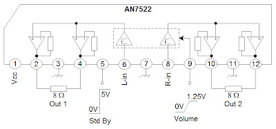 |
| Schematic AN7522 |
 |
| AN7523 amplifier schematic |
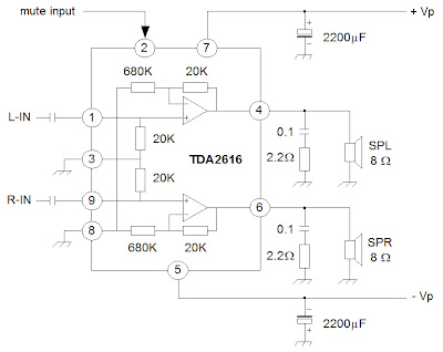 |
| Schematic TDA2616 |
