Wednesday, October 16, 2013
LM3914 IC based on Simple Battery Tester
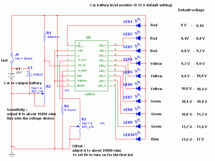
 This circuit employs the popular and easy to find LM3914 IC. This kind of IC is quite very simple to drive, requires no voltage regulators (it features a built in voltage regulator) and can be powered from almost every resource.
This LM3914 IC based on Simple Battery Tester is very simple to explain:
Once the test switch is pushed, the Car battery voltage is supply into a high impedance voltage divider. His function is to divide 12V to 1, 25V (or lower values to reduced values). This solution is much better than enabling the internal voltage regulator set the 12V sample voltage to be feed into the internal voltage divider simply because it cannot regulate 12V if the voltage falls lower (linear regulators only step down). Simply wiring with no change, the regulator provides secure 1, 25V which can be fed into the precision internal resistor cascade to create sample voltages to the internal comparators.
In any case the default establishing let you to determine voltages between 8 and 12V however you can measure even from 0V to 12V setting the offset trimmer to 0 (but i believe that below 9 volt your vehicle would not start). There is a smoothing capacitor (4700uF 16V) it is used to adsorb EMF noises produced from the ignition coil if youre testing the battery during the engine working. Diesel engines would not need it, but i am not sure. If you want more a level graph rather than a bar graph simply disconnect pin 9 on the IC (MODE) from power. The calculations are usually simple (default).
Related Posts : based,
battery,
ic,
lm3914,
on,
simple,
tester
Subscribe to:
Post Comments (Atom)
nice job!
ReplyDeletecan you explain how you did it?
I have try to understand using the datasheet - without any success
what does any resistor mean?
how can I change the resistors to make it work from 10-12V (and not 8-12)?
hope you will see this and help
Thanks ,