Showing posts with label alarm. Show all posts
Showing posts with label alarm. Show all posts
Friday, November 8, 2013
Alarm Indicator for High Temperature Reading
The circuit has been designed to provide an alarm with the use of a buzzer when sensing high temperature by using a thermistor.
These bipolar transistors form a Darlington pair to produce a very high current gain that is much higher then each transistor taken separately. This is made possible when the current amplified by the first transistor is further amplified by the second transistor. The overall gain is equal to the two individual gains multiplied together.A Darlington pair is designed in such a way that the collectors of both transistors are attached together and the emitter of the first transistor is directly coupled to the base of the second or output transistor. The base current of the output transistor is equal to the emitter current of the input transistor. When several transistors are used, it can form a cascade connection and the total current amplification factor will be very high since it is a product of current amplification factor of respective transistors.
Alarm Indicator for High Temperature Reading Schematic

When the Darlington pair conducts in this circuit, it causes the relay K1 to close thereby triggering the buzzer to produce sound due to the increase in temperature that is more than the predetermined value. The location of the thermistor should be far enough from other components of the circuit to prevent inhibiting their temperature. The circuit is powered by a 9 V battery for ease of transportation but a dedicated power supply can be provided is the circuit would be in a permanent location. A load, like a lamp or a LED, can also be connected to the contacts of the relay to produce a light indication or notification of the occurrence of excess temperature. Since the circuit is well insulated, the thermistor, connected to the circuit with a plated cable, can be submerged to water to cool down or reset the sensitivity and will not cause any short circuit. Doing this will regulate the trimmer.
This circuit can be designed not only by setting a detection of high temperature but can also be modified to be set on detection of low temperature in some industries. It can be used for refrigeration, walk-in freezer, or walk-in cooler systems and other environments that are sensitive in temperature. Some circuits incorporating high temperature alarm modules are being used in motor vehicles to detect the occupancy wherein the temperature element senses a highly dangerous temperature in the passenger compartment of a motor vehicle and energizes the occupancy sensor to determine the presence or absence of an occupant. In the absence of the occupant, the sensor de-energizes after a period of time while an audible alarm is triggered to create attention to the motor vehicle in the presence of an occupant. This type of alarm can be reset with the use of a key.
Having a temperature alarm can provide benefits like protecting valuable equipment due to high temperature, low temperature, or sometimes high humidity. Other high temperature program can be used to protect against air conditioning failure or against the heating system to turn off. On the contrary, low temperature program can be used against heating system failure by aiding to prevent frozen pipes. The alarm can also reduce downtime by receiving a telephone call and being notified of a possible power loss or failure before the damage occurs in an equipment.

The Darlington pair used in the circuit can also be used as an important component in a switching device while high power Darlington transistors can be used in emergency power supply and in control circuits for AC and DC motor control. These applications make the Darlington suitable for switching large currents in high power circuits.
- Thermistor – one type of resistor used as temperature-sensing element which demonstrates a large change in resistance proportional to a small change in temperature because of the composition of its semiconductor material.
- BC550 – an NPN general purpose transistor with low current and low voltage used for low noise stages in audio frequency equipment.
These bipolar transistors form a Darlington pair to produce a very high current gain that is much higher then each transistor taken separately. This is made possible when the current amplified by the first transistor is further amplified by the second transistor. The overall gain is equal to the two individual gains multiplied together.A Darlington pair is designed in such a way that the collectors of both transistors are attached together and the emitter of the first transistor is directly coupled to the base of the second or output transistor. The base current of the output transistor is equal to the emitter current of the input transistor. When several transistors are used, it can form a cascade connection and the total current amplification factor will be very high since it is a product of current amplification factor of respective transistors.
Alarm Indicator for High Temperature Reading Schematic
When the Darlington pair conducts in this circuit, it causes the relay K1 to close thereby triggering the buzzer to produce sound due to the increase in temperature that is more than the predetermined value. The location of the thermistor should be far enough from other components of the circuit to prevent inhibiting their temperature. The circuit is powered by a 9 V battery for ease of transportation but a dedicated power supply can be provided is the circuit would be in a permanent location. A load, like a lamp or a LED, can also be connected to the contacts of the relay to produce a light indication or notification of the occurrence of excess temperature. Since the circuit is well insulated, the thermistor, connected to the circuit with a plated cable, can be submerged to water to cool down or reset the sensitivity and will not cause any short circuit. Doing this will regulate the trimmer.
This circuit can be designed not only by setting a detection of high temperature but can also be modified to be set on detection of low temperature in some industries. It can be used for refrigeration, walk-in freezer, or walk-in cooler systems and other environments that are sensitive in temperature. Some circuits incorporating high temperature alarm modules are being used in motor vehicles to detect the occupancy wherein the temperature element senses a highly dangerous temperature in the passenger compartment of a motor vehicle and energizes the occupancy sensor to determine the presence or absence of an occupant. In the absence of the occupant, the sensor de-energizes after a period of time while an audible alarm is triggered to create attention to the motor vehicle in the presence of an occupant. This type of alarm can be reset with the use of a key.
Having a temperature alarm can provide benefits like protecting valuable equipment due to high temperature, low temperature, or sometimes high humidity. Other high temperature program can be used to protect against air conditioning failure or against the heating system to turn off. On the contrary, low temperature program can be used against heating system failure by aiding to prevent frozen pipes. The alarm can also reduce downtime by receiving a telephone call and being notified of a possible power loss or failure before the damage occurs in an equipment.
The Darlington pair used in the circuit can also be used as an important component in a switching device while high power Darlington transistors can be used in emergency power supply and in control circuits for AC and DC motor control. These applications make the Darlington suitable for switching large currents in high power circuits.

Tuesday, October 22, 2013
Auto Alarm Schematic
In operation, the alarm circuit allows a 0 - 47 second time delay, as determined by the R1 /C1 combination, after the switch is armed to allow the vehicles motion sensor to settle down. This allows you time to get a bag of groceries out of the trunk and not have the hassle of juggling the groceries and the key switch at once.
During the time delay, half of LED1, which is actually a single, bi-colored, three-legged common cathode device, lights green. At the same time, pins 8 and 4 of U2 (a 555 oscillator/timer) are held low by Ul (a 3905 oscillator/timer), causing the alarm to remain silent. Once the delay is over, LED1 turns red, indicating that the circuit is armed.
Auto Alarm Schematic Circuit Diagram

At that point, a ground at pin 2 of U2 forces pin 3 of U2 high, closing the contacts of Kl and sounding the siren for a time duration determined by R4 and C2. Once the time has elapsed, pin 3 is pulled low, Kl opens, and the circuit is again ready to go. The circuit can be manually reset by the simple expedient of opening and closing the key switch. Potentiometer R3 controls the LEDs illumination intensity.
Diode D1 ensures that the green segment of LED1 is fully extinguished when Ql is turned on-which turns the LED to red. Resistors R4 and R5 must be connected to the + V bus. not to pin 7 of Ul. otherwise U2 will mysteriously trigger itself each time the initial delay ends.
During the time delay, half of LED1, which is actually a single, bi-colored, three-legged common cathode device, lights green. At the same time, pins 8 and 4 of U2 (a 555 oscillator/timer) are held low by Ul (a 3905 oscillator/timer), causing the alarm to remain silent. Once the delay is over, LED1 turns red, indicating that the circuit is armed.
Auto Alarm Schematic Circuit Diagram
Diode D1 ensures that the green segment of LED1 is fully extinguished when Ql is turned on-which turns the LED to red. Resistors R4 and R5 must be connected to the + V bus. not to pin 7 of Ul. otherwise U2 will mysteriously trigger itself each time the initial delay ends.
Saturday, October 19, 2013
Auto Turn Off Alarm With 8 Minute Delay
This circuit uses a NE555 timer and CD4020B. When +12 Vdc is applied to the circuit, the output of IC2 is set low via C2, which turns on the relay, and IC1, a pulse generator.
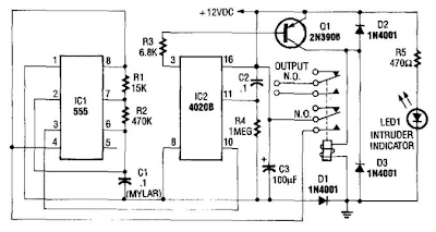 IC1 pulses counter IC2. After 8192 clocks, IC2 output (pin 3) goes high, cuts off Q2, and completes the cycle.
Auto Turn-Off Alarm With 8-Minute Delay Circuit Schematic
Tuesday, October 15, 2013
Fire Alarm using NE555 and temperature sensor

This is a simple series of fire alarms. In this series used NE555 timer and temperature sensor to detect high temperatures. The working principle of this temperature sensor that is when the temperature is high around the sensor then there is resistance on the sensor to be small.
However if the low temperature then the resistance will be high. If the resistance of small sensors, the voltage supply will be able to flow past the sensor and activate the transistor.

IC1 NE555 as a regulator of the audio frequency. Transistors 1 and 2 are used as a driver IC1. Output (pin 3) of IC1 would trigger a transistor base T3 (SL100), which drives the speaker to produce sound the alarm. Frequency NE555 depending on resistance values of R5 and R6 and the capacitance sensor C2 temperature. When the temperature gets hot, would provide a low resistance so that supply voltage can flow into the base of transistor T1 through a diode D1 and R2.
Capacitor C1 will charge a positive voltage so that it will increase the time when the fire alarm. The greater the value of C1, the greater the positive bias applied to the base of transistor T1 (BC548). T1 collector coupled to the base transistor T2, transistor T2 provides a positive voltage to pin 4 (reset) from IC1 (NE555). Resistors R4 will make IC1 NE555 continued to be active despite no positive voltage flowing.
Tuesday, October 1, 2013
Alarm LED Light Circuit
This circuit yearn for act the performance of the equipment,otherwise Check the fuse here the circuit.The circuit is diminutive and the power supply voltage of all kinds. It demonstrate with LED, 2-color in individual. Which is cathode universal kind,the anode has two separate terminals. If the circuit is functioning well LED, it revealed in wet behind the ears colour.The display is red, as the fuse into the circuit is damaged.The resistor R1 limits the current to gush through the LED is roughly 2 mA.This is an adequate amount to produce the LED light.If it lowers the R1 down, the LED light up.
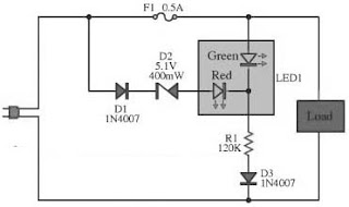 |
| Alarm LED Light Circuit Diagram |
In the conventional setup of the circuit and The fuse is not damaged. The zener diode to prevent the green and red LED illumination up in chorus.Zener diode prevents the LED is simple and red illumination all together.
The piercing efficiency LED, as soon as connected trendy like. The red LED uses high-pressure, so with the intention of single green LED illumination up only. Diodes D3 and D4 wish prevent dodgy instead of the LED. While the semi cycle downbeat voltage of the alternating current voltage.However, if the DC supply voltage.I act not retain to manage diode protection.
Subscribe to:
Posts (Atom)