Showing posts with label usb. Show all posts
Showing posts with label usb. Show all posts
Thursday, October 31, 2013
Simple USB player circuit with PCM2902
Usb series player is an electronic device or electronic circuit that functions as an MP3 player that is stored on a storage device such as USB flash.

In this usb circuit using an IC as a modifier of digital voice data into analog so that it can be applied to a headphone, or again through the power amlplifier strengthened so that it can be heard through the speakers. IC used in this circuit using IC PCM2902 as a modifier of a digital data into analog data storage.
Below is a schematic diagram of a USB player.
 |
| Schematic usb player |

Simple USB player circuit with PCM2902
Usb series player is an electronic device or electronic circuit that functions as an MP3 player that is stored on a storage device such as USB flash.
In this usb circuit using an IC as a modifier of digital voice data into analog so that it can be applied to a headphone, or again through the power amlplifier strengthened so that it can be heard through the speakers. IC used in this circuit using IC PCM2902 as a modifier of a digital data into analog data storage.
Below is a schematic diagram of a USB player.
|
| Schematic usb player |
Saturday, October 12, 2013
USB FM transmitter circuit
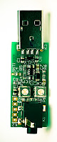
Heres a simple VHF FM transmitter that could be used to play audio files from an MP3 player or computer on a standard VHF FM radio. The circuit use no coils that have to be wound. This FM transmitter can be used to listen to your own music throughout your home. When this FM transmitter used in the car, there is no need for a separate input to the car stereo to play back the music files from your MP3 player.
To keep the circuit simple as well as compact, it was decided to use a chip made by Maxim Integrated Products, the MAX2606 [1]. This IC from the MAX2605-MAX2609 series has been specifically designed for low-noise RF applications with a fixed frequency. The VCO (Voltage Controlled Oscillator) in this IC uses a Colpitts oscillator circuit. The variable-capacitance (varicap) diode and feedback capacitors for the tuning have also been integrated on this chip, so that you only need an external inductor to fix the central oscillator frequency.
 |
| USB FM transmitter schematics |
It is possible to fine-tune the frequency by varying the voltage to the varicap. Not much is demanded of the inductor, a type with a relatively low Q factor (35 to 40) is sufficient according to Maxim. The supply voltage to the IC should be between 2.7 and 5.5 V, the current consumption is between 2 and 4 mA. With values like these it seemed a good idea to supply the circuit with power from a USB port.
A common-mode choke is connected in series with the USB connections in order to avoid interference between the circuit and the PC supply. There is not much else to the circuit. The stereo signal connected to K1 is combined via R1 and R2 and is then passed via volume control P1 to the Tune input of IC1, where it causes the carrier wave to be frequency modulated. Filter R6/C7 is used to restrict the bandwidth of the audio signal. The setting of the frequency (across the whole VHF FM broadcast band) is done with P2, which is connected to the 5 V supply voltage.
The PCB designed uses resistors and capacitors with 0805 SMD packaging. The size of the board is only 41.2 x 17.9 mm, which is practically dongle-sized. For the aerial an almost straight copper track has been placed at the edge of the board. In practice we achieved a range of about 6 metres (18 feet) with this. There is also room for a 5-way SIL header on the board. Here we find the inputs to the 3.5 mm jack plug, the input to P1 and the supply voltage. The latter permits the circuit to be powered independently from the mains supply, via for example three AA batteries or a Lithium button cell. Inductor L1 in the prototype is a type made by Murata that has a fairly high Q factor: minimum 60 at 100 MHz.
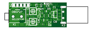 |
| Layout PCB USB FM transmitter |
Take care when you solder filter choke L2, since the connections on both sides are very close together. The supply voltage is connected to this, so make sure that you don’t short out the USB supply! Use a resistance meter to check that there is no short between the two supply connectors before connecting the circuit to a USB port on a computer or to the batteries.
P1 has the opposite effect to what you would expect (clockwise reduces the volume), because this made the board layout much easier. The deviation and audio bandwidth varies with the setting of P1. The maximum sensitivity of the audio input is fairly large. With P1 set to its maximum level, a stereo input of 10 mVrms is sufficient for the sound on the radio to remain clear. This also depends on the setting of the VCO. With a higher tuning voltage the input signal may be almost twice as large (see VCO tuning curve in the data sheet). Above that level some audible distortion becomes apparent. If the attenuation can’t be easily set by P1, you can increase the values of R1 and R2 without any problems.
Measurements with an RF analyzer showed that the third harmonic had a strong presence in the transmitted spectrum (about 10 dB below the fundamental frequency). This should really have been much lower. With a low-impedance source connected to both inputs the bandwidth varies from 13.1 kHz (P1 at maximum) to 57 kHz (with the wiper of P1 set to 1/10).
In this circuit the pre-emphasis of the input is missing. Radios in Europe have a built-in de-emphasis network of 50 μs (75 μs in the US). The sound from the radio will therefore sound noticeably muffled. To correct this, and also to stop a stereo receiver from mistakenly reacting to a 19 kHz component in the audio signal, an enhancement circuit Is published elsewhere in this issue (Pre-emphasis for FM Transmitter, also with a PCB). Author: Mathieu Coustans, Elektor Magazine, 2009
MP3 FM Transmitter Parts List
Resistors (all SMD 0805)
R1,R2 = 22kΩ
R3 = 4kΩ7
R4,R5 = 1kΩ
R6 = 270Ω
P1 = 10kΩ preset, SMD (TS53YJ103MR10 Vishay Sfernice, Farnell # 1557933)
P2 = 100kΩ preset, SMD(TS53YJ104MR10 Vishay Sfernice, Farnell # 1557934)
Capacitors (all SMD 0805)
C1,C2,C5 = 4μF7 10V
C3,C8 = 100nF
C4,C7 = 2nF2
C6 = 470nF
Inductors
L1 = 390nF, SMD 1206 (LQH31HNR39K03L Murata, Farnell # 1515418)
L2 = 2200Ω @ 100MHz, SMD, common-mode choke, 1206 type(DLW31SN222SQ2L Murata, Farnell #1515599)
Semiconductors
IC1 = MAX2606EUT+, SMD SOT23-6 (Maxim Integrated Products)
Miscellaneous
K1 = 3.5mm stereo audio jack SMD (SJ1-3513-SMT
CUI Inc, DIGI-Key # CP1-3513SJCT-ND)
K2 = 5-pin header (only required in combination with 090305-I pre-emphasis circuit)
K3 = USB connector type A, SMD (2410 07 Lumberg, Farnell # 1308875)
Notice. The use of a VHF FM transmitter, even a low power device like the one described here, is subject to radio regulations and may not be legal in all countries.
source [ Link ]
source [ Link ]
Tuesday, October 8, 2013
USB SPDIF DAC with IC PCM 2902
The tool that I made and I discuss in this article I give the name USB SPDIF DAC Every word in the name corresponds to the function of the tool that I made this.
USB, this device serves to take the music information in digital form from a computer via the USB port
SPDIF, this tool can output digital music information received through the USB port, through the SPDIF output terminal that is also present in this device, so if you have a DAC that does not have a USB input, you can still use and do not need to buy a new DAC that has an input USB.
DAC, this tool can convert the digital signals derived from the USB port, an analog signal, which you can connect to the amplifier to the ahirnya you can hear the speaker
Scheme of the USB DAC can be seen in Figure 1 below.USB, this device serves to take the music information in digital form from a computer via the USB port
SPDIF, this tool can output digital music information received through the USB port, through the SPDIF output terminal that is also present in this device, so if you have a DAC that does not have a USB input, you can still use and do not need to buy a new DAC that has an input USB.
DAC, this tool can convert the digital signals derived from the USB port, an analog signal, which you can connect to the amplifier to the ahirnya you can hear the speaker
 |
| Click to view larger. | Figure 1 |
As you can see on the schematic in Figure 1 above, which is the heart of the circuit is IC USB DAC PCM2902 made by Texas Instrument, other than that I also added a digital SPDIF output isolation transformer on from this series. 2902 PCM encoding decoding work on the principle that generally abbreviated as word CODEC.
The new circuit will work when the USB input port terminal in the circuit connected to the computer, at this voltage 5V on the USB port of any computer will be triggering the circuit to begin work, and vice versa when the computer is turned off then the circuit will be in standby mode to wait until there is more tension 5V from USB port of computer.
When the received voltage is 5V USB port the computer then the circuit will begin to receive the digital data files during the grace period of 1 ms, all data received during the period of time of 1 ms is called a frame, the data in the first frame is stored in a memory buffer that is in the PCM2902, then the circuit will start the second frame as well as long lead times for 1mS, 1mS a second after the first data from the file will be converted into analog signals for analog terminal is then removed through out the pin 15 and 16 of the PCM2902, other than that this digital signal simultaneously will also excreted through the DOUT terminal pin 25 of the PCM2902 DAC to be connected to older products that do not have a USB input terminal. In addition to functioning as a DAC, PCM2902 actually also has other functions such as setting volume level and ADC, but the circuit that I developed is only aimed for the ADC and the conversion from USB to SPDIF.
Proposed Power Supply For USB SPDIF DAC
Power Supply that I use in this project using the configuration has been proven able to tame the hum in the tube 26, the power supply has karakater very stable, low noise and low impedance, but complicated to make, so for the purposes of this project I recommend another series that is not as complicated Heater power supply 26, but the quality is still better than most of the power supply kit used in the DAC in general, Figure 2 below is the recommendation power supply for USB DAC this project.
 |
| Click to view larger. | Figure 2 |
1. Diode bridge and capacitor input filter
2. TL431 as the reference voltage
3. OP Amp OP27 as the error amplifier
4. BD139 transistor as a pass transistor This configuration is basically the general configuration of a linear regulator series, very much the regulator IC using this configuration, but the circuit in Figure 2 above has several advantages that are not owned by the regulator circuit in the form of IC a) high stability, since it uses a reference voltage source of good quality is TL431, and therefore not in a package with a pass transistor, the heat of the pass transistor can not seep into the source of reference voltage and makes it unstable, this sort of thing happens in IC voltage regulator. b) Using the Op Amp high quality, which in this case OP27, so it is not easy to oscillate as the OpAmp used in the regulator IC. c) If there is a chance you could also replace the TL431 or OP27 Op Amp voltage source and another that is expected to be better than either of these components.
 |
| Series of the finished PCB, top view |
 |
| IC PCM2902 |
Sunday, October 6, 2013
Making PC USB LCD controller project
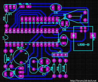
 This really a work that so cool if you like modif PC. So this is a USB interface for alphanumeric LCD display like 4 × 20 which can be controlled with LCD Smartie program. USB interface is implemented by using PIC18F2550 microcontroller, Using USB LCD modules. Below is a project of the USB LCD controller.
Schematic circuit and PCB design

source | link
Thursday, October 3, 2013
USB Audio Interface based DAC PCM2902

This is the circuit quality preamplifier with built-in USB DAC for my Leachamp power amplifier. Scheme is PCM2902 datasheet. Circuit includes DAC and ADC, SPDIF input and output of HID and with 3 buttons + MUTE, VOL-and VOL.
For playback of high quality needed for external low-drop voltage stabilizer for the DAC. LP2951CM DAC is used, which was readily available in local stores. Output voltage is fixed at about 3.7 V with two resistors. Circuit board is designed with regard to the placement of good land, and the separation of digital and analog ground. These earth are connected in a single point in a USB connector.
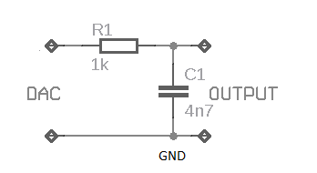
The PCM2902 data sheet is recommended to connect a low pass filter the DAC output to filter high frequencies above audioband produced by the conversion of oversampling. Digital integrated circuits that includes LPF filter frequency above 100 kHz. In the Notes application filter on the pages of the manufacturer recommends first-order LPF (simple RC) or 2 nd order with amplifiers operating as a preamp that works well. I simple RC LPF with the recommended values R and C 1k 4N7. It is best to use the scroll-type ceramic capacitor in place. I did not hear the difference in sound between the connection filter or not, but with respect to other components in an audio chain is best used. For maximum cutoff frequency that can change the capacitor value of 3n3
Friday, September 13, 2013
Type of USB connectors
USB connector there are only 2 kinds, namely the connector type A and type B connector, as shown below. Type A connector used to connect the USB cable into the USB terminal on the back of the computer the last few years of production. Type B connector used to connect the USB cable into the USB terminal on the equipment, for a simple USB devices, such as mouse, usually do not use the connector B, to save cost in the cable directly connected to the inside of the mouse.
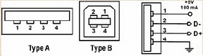
Specified in the standard reference pesyaratan very strict to USB cable, not just the cable can be used, all the more for USB full-speed transfer of data to 1.2 Mega bps. So that the USB cable always sold as a ready-made, one end attached to the connector type A and the other end attached to the connector type B, no one sells it off the USB connector.
On the computer, usually there are two terminals for connector type A, so it can easily be paired with 2 pieces of USB devices. Manufacturing company that makes the mother board there is an additional USB terminal, you can buy if you want to add more than 2 USB devices. USB terminal on the computer named as Root Hub Another way is to use a USB hub as shown in the figure, in this way can one USB terminal on the broken into four.

Each of these fractions can also be connected to another USB Hub, as well as onward connection to connect to as many as 7 levels, which could eventually connect to 128 pieces of USB devices!
Subscribe to:
Posts (Atom)