Showing posts with label digital. Show all posts
Showing posts with label digital. Show all posts
Sunday, December 15, 2013
Create a Digital Volume Control Circuit
This series is the volume of the digital amplifier That is used on or tone control. This series ic type using DS1669 Digital Pot IC specifically for this volume match. a series of settings used at the middle-class amplifier That small powerless under 50 watts. volum11 components: C1 = 0.1uf Ceramic, IC = IC DS1669 Digital Pot, S1 / S2 = digital swicth Or you can use the series to this one: volum2 The Work: The digital volume control IC uses 9.
 |
| Click to view larger. |
Required to operate the series voltage regulator is 12 volts. IC1 (555) is very good to work as a flip-flop. Frequency or period can be determined with selecting value of resistor R44, R45 is combined with a capacitor C6. In this series has a 0.3 second period. IC2 is used to Decrease or increase of the calculation. In the series of this mode is used to raise up and down mode is used to Decrease the volume.
While IC4 and IC3 has a 16-channel, analogue multiplexers, while working as an analog switch. IC3 is used as in the series of level indicator while IC4 is used as potentiometer. After the next power in the on-it, and the switch S1 is pressed to reset. When the switch S2 is pressed, the IC2 and the balance in the form of output legs responded B, C, and D in CMOS IC2. Output B, C and D control line inputs IC2 and IC3, and the chosen one, the 16-channel output, by turning on the analogue. In this series, IC4 is used as the potentiometer is connected to the That resistor 15 (R9 to R23) each of the 16 input pins and resistor / capacitor combination with C2, C3 and R7 to the output.
Switch S2 is used to raise and switch S3 is used to Decrease the volume. Electrolyte capacitor of 1uF (C4) is used to Prevent the occurrence of noise. While the R8 and the resistor R6 is used to Prevent Tension on the half-supply voltage in order to avoid distortion of the audio signal coming from the preamplifier. Meanwhile, capacitor C2, C3 and resistor R7 is provided to filter the audio. Happy work, hopefully successfully.
COMPONENT LIST:

Tuesday, November 5, 2013
Digital Led Chaser circuit diagram
 Digital Led Chaser circuit diagram
This particular circuit employs electronic digital circuits say for example a demultiplexer and also a binary table to build designs of "moving" led lights. This simple circuit is actually awesome while employed in the dark or light up an indicator of a few type, because it produces a awesome design which attracts the eyesight.
The primary component of the circuit is a demultiplexer 74ls138, we can be connected minimally important bits on the output on the counter, which will pick out one of many pins of the demultiplexer as being the output, lighting effects the led connected to the item. The counter can be wired only to be counted, plus a time clock beat is necessary to do that operate (the time clock circuit isnt involved, but almost any can do, if it is not very noisy)
One variation to apply is to connect the most major bit of that counter to a different a line leds, allowing and also disabling one of these so the design could observe 16 leds instead of the only 8 established these.
Wednesday, October 30, 2013
Digital tone control with MAX5406
The series will I make here is a series regulator of Volume, Bass, and Balance Trable Digital (Tone Control). The core of this circuit is an IC-type output from the Manufacturer Maxim MAX5406, while the IC is an audio processor that comes with the interface switch hit for Tone Control setting above. The circuit scheme is as follows:
The scheme above uses very little supporting components and this makes can be made with a mini size of a matchbox only even if using all SMD components can be reduced in size by half for this time I will only give a simple layout made, following picture:


 |
| layout components |
Friday, September 27, 2013
Digital control system applications
Digital Control System is a branch of the control system with continuous time processes in the region associated with the digital controller as the controller of the control elements that control systems and computing discrete time. Depending on requirements, a digital controller can be shaped microcontroller and ASIC to a standard desktop computer. Because the digital computer system is discrete, then the Laplace transform is used in the control system is replaced with the Z-transform. Therefore, you must understand about the concept of continuous time and discrete time concept.
 |
| Flow Chart - Digital Control system applications |
Digital computer also has a limited precision (See quantization) extra care needed to ensure that errors in the coefficients, A / D conversion, D / A conversion, etc. do not produce unwanted effects or planned.
The application of digital control can easily be done when used in a feedback form. Since the creation of the first digital computer in the early 1940s the price of digital computers has dropped significantly. The reason this is one of the many reasons for the application of digital control systems for the control of the control system. Other reasons:
Flexibile: easy to configure and reconfigure through software
* Scalable: can be set up programs tailored to the limits of memory or storage space at no extra cost
* Adaptable: program parameters can be changed with the times
* Static operation: digital computers are much more susceptible to environmental conditions rather than of capacitors and inductors
Sunday, September 15, 2013
Digital Clock with Timer and Solar Panel Regulator
This is a combination digital clock timer and solar panel charge controller used to maintain a deep cycle battery from a solar panel. The timer output is used to control a 12 volt load for a 32 minute time interval each day. Start time is set using 9 dip switches and ends 32 minutes later. The 32 minute duration is set by selecting the 5th bit (2^5 = 32) of a 4040 binary counter (pin 2). The timer also has a manual toggle switch so the load can be manually switched on or off and automatically shuts off after 32 minutes. The time duration can be longer or shorter (8,16,32,64,128,256 minutes etc.) by selecting the appropriate bit of the counter. The timer circuit is shown in the lower schematic just above the regulator.
Basic Clock Circuit diagram
The basic clock circuit (top schematic below) is similar to the binary clock (on another page) and uses 7 ICs to produce the 20 digital bits for 12 hour time, plus AM and PM. A standard watch crystal oscillator (32,768) is used as the time base and is divided down to 1/2 half second by the 4020 binary counter. One half of a 4013 data latch is used to divide the 1/2 second signal by 2 and produce a one second pulse that drives the seconds counter (74HC390 colored purple). The minutes are advanced by decoding 60 seconds (40 + 20) and then resetting the seconds counter to 0 and at the same time advancing the minutes counter. The same procedure is used to advance the hours. The second half of the 4013 latch is used to indicate AM or PM and is toggled by decoding 13 hours and resetting the hours to 0 and then advancing the hours to "one".
Clock Display Circuit diagram
The clock display circuit is shown in the second drawing below and uses 6 more ICs to decode the binary data and drive four seven segment LED displays. The 10s of hours digit is driven with a single 3904 transistor. Two multiplexer circuits (4053) are used to manually select either minutes or seconds for the right two display digits. The two switches shown between the 4053s and below the left 4053 are both part of one DPDT switch which selects either seconds or minutes for the 1X and 10X digits. This switch is shown in the seconds position and the hours digits are blanked with a low signal on pin 4 of the 4511.
The display can also be toggled on and off (totally blank) using a set/reset latch made from a couple 74HC00 NAND gates. A momentary DPDT switch is used to control the latch and toggle the display on or off. The second pole of this switch is used on the upper drawing (connected to the run/stop switch) to set the hours and minutes. Thus this same switch performs both functions of blanking the display and setting the time. The run/stop switch is shown in the normal running mode and supplies a low signal to a NAND gate which prevents accidental setting the time while the clock is running.
Clock Timer Circuit diagram
The run/stop switch also turns on the display (through the diode D2) when in the stop position. The procedure for setting the clock would be to set the (run/stop) switch the stop position and the (seconds/minutes) switch to the minutes position. Then toggle the momentary switch to set minutes and hours of the current time plus one minute. The clock can then be started with the run/stop switch at precisely the right time (+/- 0.5 seconds).
Voltage Regulator (13.6 volts)
The voltage regulator in the lower drawing maintains the battery at 13.6 volts and also supplies the clock and timer circuits with 4.3 volts. The charge LED indicator only comes on when the regulator is supplying max charge to the battery. When the battery voltage reaches 13.6 the regulator reduces the current to whatever is necessary to maintain the voltage and the charge indicator will turn off. The unit I built also included a battery condition indicator (voltmeter using 4 LEDs) to indicate the battery condition so that a failure of the regulator would be indicated by the charge indicator LED turned off and less than 4 LEDs lit on the voltmeter.
Basic Clock Circuit diagram
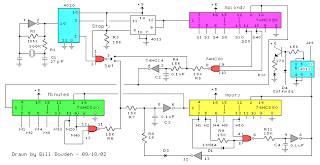 |
The basic clock circuit (top schematic below) is similar to the binary clock (on another page) and uses 7 ICs to produce the 20 digital bits for 12 hour time, plus AM and PM. A standard watch crystal oscillator (32,768) is used as the time base and is divided down to 1/2 half second by the 4020 binary counter. One half of a 4013 data latch is used to divide the 1/2 second signal by 2 and produce a one second pulse that drives the seconds counter (74HC390 colored purple). The minutes are advanced by decoding 60 seconds (40 + 20) and then resetting the seconds counter to 0 and at the same time advancing the minutes counter. The same procedure is used to advance the hours. The second half of the 4013 latch is used to indicate AM or PM and is toggled by decoding 13 hours and resetting the hours to 0 and then advancing the hours to "one".
Clock Display Circuit diagram
 |
The clock display circuit is shown in the second drawing below and uses 6 more ICs to decode the binary data and drive four seven segment LED displays. The 10s of hours digit is driven with a single 3904 transistor. Two multiplexer circuits (4053) are used to manually select either minutes or seconds for the right two display digits. The two switches shown between the 4053s and below the left 4053 are both part of one DPDT switch which selects either seconds or minutes for the 1X and 10X digits. This switch is shown in the seconds position and the hours digits are blanked with a low signal on pin 4 of the 4511.
The display can also be toggled on and off (totally blank) using a set/reset latch made from a couple 74HC00 NAND gates. A momentary DPDT switch is used to control the latch and toggle the display on or off. The second pole of this switch is used on the upper drawing (connected to the run/stop switch) to set the hours and minutes. Thus this same switch performs both functions of blanking the display and setting the time. The run/stop switch is shown in the normal running mode and supplies a low signal to a NAND gate which prevents accidental setting the time while the clock is running.
Clock Timer Circuit diagram
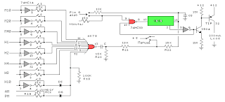 |
The run/stop switch also turns on the display (through the diode D2) when in the stop position. The procedure for setting the clock would be to set the (run/stop) switch the stop position and the (seconds/minutes) switch to the minutes position. Then toggle the momentary switch to set minutes and hours of the current time plus one minute. The clock can then be started with the run/stop switch at precisely the right time (+/- 0.5 seconds).
Voltage Regulator (13.6 volts)
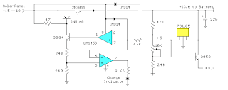 |
The voltage regulator in the lower drawing maintains the battery at 13.6 volts and also supplies the clock and timer circuits with 4.3 volts. The charge LED indicator only comes on when the regulator is supplying max charge to the battery. When the battery voltage reaches 13.6 the regulator reduces the current to whatever is necessary to maintain the voltage and the charge indicator will turn off. The unit I built also included a battery condition indicator (voltmeter using 4 LEDs) to indicate the battery condition so that a failure of the regulator would be indicated by the charge indicator LED turned off and less than 4 LEDs lit on the voltmeter.
Subscribe to:
Posts (Atom)