Monday, September 30, 2013
Mini Metronome
Linear scale-Small size 40 to 208 beats per minute
Mini Metronome Circuit diagram:
Notes:
- Q1 & Q2 provide linear frequency operation of IC1 following P1 resistance variation.
- Q3 was added in order to obtain a louder click, similar to clockwork metronomes.
- 12V micro battery was used to obtain more output power and more compactness.
- Rotate P1 fully towards R2, then set R1 to obtain 40 beats per minute (compare with another metronome).
- Rotate P1 fully towards R3, then set R4 to obtain 208 beats per minute.
- Finally mark the entire scale with the usual metronome steps as following:
- 40 - 42 - 44 - 46 - 48 - 50 - 52 - 54 - 58 - 60 - 63 - 66 - 69 - 72 - 76 - 80 - 84 - 88 - 92 - 96 - 100 - 104 - 108 - 112 - 116 - 120 - 126 - 132 - 138 - 144 - 152 - 160 - 168 - 176 - 184 - 192 - 200 - 208.
Parts:
P1______100K Linear Potentiometer
R1_______10K 1/2W Trimmer Cermet
R2_______10K 1/4W Resistor
R3______330K 1/4W Resistor
R4_______50K 1/2W Trimmer Cermet
R5______100K 1/4W Resistor
R6,R7_____1K 1/4W Resistor
C1________1µF 63V Polyester Capacitor
C2_______10nF 63V Polyester Capacitor
C3_______47µF 25V Electrolytic Capacitor
IC1_____NE555 General purpose timer IC
Q1,Q2___BC560 45V 100mA Low noise High gain PNP Transistors
Q3_____ZTX753 100V 2A PNP Transistor
SW1______SPST Switch (Ganged with P1)
SPK______8 Ohm 40mm. Loudspeaker
B1_____12V Battery (MN21, GP23A or VR22 type)
7812 voltage stabilizer
To obtain a pure DC voltage, then we must consider the regulation voltages and currents that we change from AC to DC current. For that we need some settings that can support our own making and its components were easy to get in the electronics market.
This is series Power Supply that can be used on trafo 5 Ampere up to 10 Amperes.
If you want to use a larger transformer than 5 Amperes transistor 2N3055 is suggested that the double for the exit of the collector current is larger and in accordance with the current out of the transformer. How pemasanganya enough in the series on all sides of the pin.
Relay Switch Activated by Tone and Signal
The essence of the circuit is for the input of tone and signal to provide an activation for the relay switch.
Circuit Diagram
The circuit created is sensitive enough to the AC signals in the input stage, where the signals are ranging above 5 mV. It will also be sensitive to react with the human voice signals having a range of frequency from 50 Hz up to 3 KHz. The human voice is a part of the human sound produced primarily by the vocal cords or vocal folds which in turn produces a voice frequency that is used for the transmission of speech.
During the absence of an input signal, the state of the 12 V relay RL1 is at OFF condition as regulated by the 10K Ohms trimmer RV1. The circuit can be made to react with its sensitivity in points A, B, & C, where a negative feedback can be placed due to the addition of band pass filter. The filter will operate only in the 1 KHz range and the circuit will only correspond at this frequency.
Parts List :
The signal and tone activated relay switch were used in a wide range of fields which includes measuring instruments, audio systems, communications equipment, and factory-automation equipment. They can also be found on telephone subscriber circuits for the polarity reversing switch, testing, and ringing functions.
- Relay – an electrically operated switch where the current flowing through the coil of the relay is creating a magnetic field which attracts a lever and changes the switch contacts, thereby making its state open or close
- BC214 – a complementary silicon planar epitaxial transistor used in AF small signal drivers and amplifiers as well as for low noise preamplifier applications due to its feature of good linearity of DC current gain
- LM741 – a general purpose single operational amplifier with features such as offset null, compensated internal frequency, voltage range with high input, good stability of temperature, and protected from short circuit
Circuit Diagram
The circuit created is sensitive enough to the AC signals in the input stage, where the signals are ranging above 5 mV. It will also be sensitive to react with the human voice signals having a range of frequency from 50 Hz up to 3 KHz. The human voice is a part of the human sound produced primarily by the vocal cords or vocal folds which in turn produces a voice frequency that is used for the transmission of speech.
During the absence of an input signal, the state of the 12 V relay RL1 is at OFF condition as regulated by the 10K Ohms trimmer RV1. The circuit can be made to react with its sensitivity in points A, B, & C, where a negative feedback can be placed due to the addition of band pass filter. The filter will operate only in the 1 KHz range and the circuit will only correspond at this frequency.
Parts List :
The signal and tone activated relay switch were used in a wide range of fields which includes measuring instruments, audio systems, communications equipment, and factory-automation equipment. They can also be found on telephone subscriber circuits for the polarity reversing switch, testing, and ringing functions.
5 1 Classic Home Theater System Energy
Low Distortion and Resonance - spokesman method is distortion- otherwise resonance-without charge, but Energy has achieved a significantly decrease distortion level, a plainly audible perfection.
The Take Classic 5.1 home theater system also offers terrific performance and great features:
- Our patented Convergent Source Module (CSM) 3-edge your way poly-titanium woofer and .75-inch hyperbolic aluminum-field tweeter -the kindness of Energy speakers
- Patented corrugated Elliptical Surround woofers create from top to toe efficiency, low distortion
- An aluminum auditorium tweeter on behalf of sonic accuracy
- Front and rear venting for additional powerful low response
Take Classic raises the piece for 5.1 narrator classification performance. It includes a powerful 200-watt subwoofer with a front-firing seaport, 8-shuffle driver and wavy Elliptical Surround™ in support of deep with the intention of you feel when much as hear. The Convergent Source Module (CSM), with its 3-shuffle poly-titanium woofer and .75-inch hyperbolic aluminum-pitch tweeter, focuses sound for clearer dialogue and stirring melody. The CSM gives soundtracks a dynamic frequency range and a colossal soundstage, used for smooth, realistic sound from every one satellite lecturer and the base channel. song and motion picture lovers rejoice. Take Classic puts the passion back into your favorite films.
Exclusive Energy® Brand Technologies
Convergent Source Module
The Convergent Source Module, before CSM, provides broad dispersion, low distortion and amazing midrange performance. The lecturers midrange and tweeter are positioned inside close proximity to individual an alternative and accomplish seeing that a single source, by this means increasing overall dispersion and falling some lobing effect. The chambering of the middle and tweeter lowers the drivers resonance, plummeting distortion.
wavy Elliptical Surround knowledge
Energys patented ridged Elliptical Surround technology (U.S. patent #6,725,967, Canadian patent #2,407,123) increases excursion, eliminates distortion and raises efficiency on woofers and subwoofers. The Elliptical Surround encompasses the conduit, allowing it to move identically concerning both instructions, follow-on in come up to nil distortion. And while standard designs are often plagued with surround dimpling, which causes them to give off in and off of segment and distort on all listening levels, Energys designs arent influenced by dimpling on all, as a substitute proprietary grooved Elliptical Surround expertise allows representing a better conduit come up, resultant trendy greater efficiency. This design as well lets the conduit do greater crest to peak movement, in this way allowing it to travel added than bend in half the distance of the competition. These attributes enable Energy woofers and subwoofers to move incredible amounts of air, ultimately allowing them to joke about drop frequencies with greater low lean-to and fidelity.
come again?s voguish the Box
A 6-example, soaring spin black place of Energy Take Classic 5.1 speakers: 4-Take satellite speakers, 1-faultlessly matched Take interior channel spokeswoman, 1-perfectly matched Take powered subwoofer; 1-owners guide.
Technical Specifications
- Frequency Response - Sat: 115Hz-20KHz; Center: 110Hz-20KHz; Subwoofer: 33Hz-150Hz +/- 3dB
- Crossover purpose - 2.9 kHz
- Sensitivity - 89dB
- Power use - Sat & core: 100 Watts; Subwoofer: 200 Watts
- Recommended Amplifier Power - 20 - 100 Watts RMS (permanent)
- Impedance - 8-ohm compatible
- Subwoofer adaptable Low Pass Filter - 40Hz-150Hz @ 18dB/octave
- Tweeter - ¾-shuffle (19 mm) Hyperbolic™ aluminum-ground
- Woofer - Sat & crux: 3-edge your way poly-titanium; junior: 8" IM cone-shaped tool with Patented grooved Elliptical Surround
- Dimensions (inches) - Sat: 6 7/8 x 4 1/8 x 4 1/8; Center: 4 1/8 x 10 1/4 x 4 1/8; Subwoofer: 12 5/8 x 12 5/8 x 12 5/8 (add 2 1/6" pro feet)
- power - Sat: 2.9 lbs; foundation: 3.2 lbs; Subwoofer: 19.7 lbs
Performance Tips:
The center channel spokeswoman needs to be alive centrally located so so as to the dialogue appears to be approach from the center of the screen. It needs to be more than or else underneath the overseer, while faithfully to it as feasible. If youon the subject of using a rear projection television, the nearly all likely option is to place it over the screen. If you say a front projection method, you have choices-rack mounting, otherwise placement on furniture, in support of illustration. It is principal, though, to place the orator so to facilitate its front frame is even with the edge of the shelf or else stand underneath it. unsolicited diffraction occurs whilst the foundation channel is too far back into a cabinet or else other exterior with edges with the aim of possibly will impede sound dispersion.
In support of not here or else utterly front channels, the distance concerning the speakers be supposed to live 6-8 feet on smallest amount for the greatest stereo imaging. The optimum extent identity is rectangular, with the speakers along solitary of the shorter walls, facing the opposite margin. If probable, figure out not place speakers hostile to a fence or else by rear of a bookshelf; corner placement is generally the most evil option. Try to keep the speakers-especially rear vented models-next to smallest amount two feet from the plane behind it, save you manipulation a vent plug. pro superlative results mounting on a rear cage up, pose the speakers so they flank the major listening area and item with regard to the front of the opportunity. They be supposed to be situated raised to a height of approximately six feet and ought to ideally give a window of six feet involving them.
The three a good number normal subwoofer locations include corners (which can upshot taking part in boomy otherwise exaggerated low frequency response), placement along a mountain, away from the corner (producing moderate low performance with increased fidelity terminated corner placement), otherwise beside a front spokeswoman (creating a better blend with the front speaker, but sacrificing overall volume). Experimentation with subwoofer placement is highly encouraged; slight adjustments can create giant differences clothed in sound reproduction. To test subwoofer placement, install it in the short term in your chief listening attitude and march around the listening space while on stage a familiar bit of melody until you catch the most excellent sounding position.
Sunday, September 29, 2013
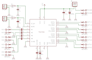
TDA7384 4 x 22W car power amplifier
TDA7384 - 4 x 22W car power amplifier
If connect to car battery where operating voltage is about 13.2V, then each channel can give 22W(4Ω) – what is more than enough for me. This amplifier I probably will use to test audio processor TDA7313 which is stil in development phase.
I didn’t find much information about this chip on the internet so I decided to built it and try on my own. As datasheets of TDA7384 says it is low distortion, low output noise, low external component count. Also has Stand-By function and Mute function. It has several protections like from output short circuit to GND or to Vs, capable to handle very inductive loads, thermal limiter, load dump voltage. TDA7384 is an AB power amplifier cased in flexiwatt25 (eagle library is included in project archive) package wich is designed for high end car radio applications. It allows rail to rail output voltage swing with no need of boot-strap capacitors.
Schematics TDA7384 |
I have followed the schematic in datasheed when building circuit. In datasheet you may also find PCB layout but it is two layered and didn’t fit to may box I’ve chosen. So I have made single sided PCB 50X100mm.
PCB TDA7384 amplifier |
As I put pins on PCB for ST-BY and Mute but I not using them, I connected these pins to VCC like it is shown in PCB view. According to datasheet St-By and Mute turns off amplifier if signal in input is lower than 3.5V. So it is recommended to connect these pins to Vcc if not used.
Maximum power dissipation of chip is 80W(Tcase=70ºC), so it can handle 4 channels working at power of 20W each. But of course chip in a box doesn’t have good ventilation so I’ve put a radiator to ensure that amplifier effectively dissipates heats. I didn’t try to load amplifier to maximum to se if it doesn’t heat up to much. But at normal sound level it stays warm what is normal.
On box amplifier |
Dont forget to put thermal paste between chip and radiator to ensure lower thermal resistance. And here we go – brand new power amplifier ready to go:
Already to use |
source: [link]
Static Detector Negative Ion Detector
A sensitive detector for static electricity based around a single Field Effect Transistor It can also be used to detect the presence of negative ions, or test a negative ion generator. This circuit utilizes the extra high input impedance of a FET, and also demonstrates the gate terminals sensitivity to changes in voltage. The gate terminal here is left open circuit,connected only to the "probe". The probe is just a few inches of bare copper wire. With no fixed DC biasing, the gate terminal will respond to micro changes in voltage. This causes a current change in the drain circuit and the meter will indicate a charge or "field strength".
Static Detector Negative Ion Detector Circuit diagram
It is important not to make this circuit on veroboard or PCB material as this will reduce the effective gate impedance. Instead use an "open" construction technique soldering each component together. The probe should not be touched directly and is best insulated in a plastic pen sleeve. As static electricity can have either a positive or negative charge, the meter used should be a centre zero type. Full scale deflection can be 1mA or 250uA for greater sensitivity. Remove the meter and use a multimeter to measure the voltage between FET drain and the preset resistor. Adjust the preset for 0 volts and then replace the meter. This will avoid "bending" the needle.
If placed in a room the meter will detect changes in static charge, positive charge deflecting the needle one way and negative the other way. You can test the circuit by placing the unit say 5 feet away from a TV set. When switched on, the meter needle should jump to full scale deflection and then drop down again. If you have a room ionizer, its output can be monitored by moving the probe in front of it. As the detector responds to changes in charge, you may need to move the detector around to see the effect, but it will prove the output from an air ionizer is working.
Static Detector Negative Ion Detector Circuit diagram
If placed in a room the meter will detect changes in static charge, positive charge deflecting the needle one way and negative the other way. You can test the circuit by placing the unit say 5 feet away from a TV set. When switched on, the meter needle should jump to full scale deflection and then drop down again. If you have a room ionizer, its output can be monitored by moving the probe in front of it. As the detector responds to changes in charge, you may need to move the detector around to see the effect, but it will prove the output from an air ionizer is working.
Complete Home theater set up speakers
Home theaters are getting to be extremely popular among American homes. This modern technology is slowly giving movie theaters a run for their money. Basic knowledge of home theater system and its basic components may be best for people who want to bring home relaxation and entertainment.
The most important consideration in the design and complete set up of your home theater is the size of the room. The home theater speakers and the other components of your home theater may need to consider the size of the room. Too small rooms for your home theater may not require so many speakers. Only three speakers may be good if the room is quite small.
Do not overload your small room; you may not be able to get the entertainment and relation you want if you feel overloaded with so many home theater speakers. Because you only need three home theater speakers in your small room, you may need to acquire the high-end brand of home theater speakers to compliment the size of the room and the other equipments for your home theater.
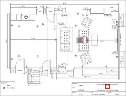
Complete home theater speaker setup |
If you have a bigger room however, the basic three home theater speakers may not be enough. You may need to put up to six speakers around the room, you may also consider complimenting your home theater speakers with subwoofer to complete the surround sound like in movie theaters. In addition to the speakers, you may also need to purchase a high-end television set which should not be smaller than 27 inches. It may not be reasonable if you buy a smaller television set because it may drown in the fineness of your home theater speakers.
Additionally, the DVD player needs to be of high quality, having progressive scan your DVD Player may help provide sharp images and flicker-free pictures for your home theater system. The home theater speakers, television and DVD player are the basic components of a home theater system especially if the room is quite small. However, for bigger room, adding home theater furniture and home theater projectors may be necessary to complete the package. Again, it may be worth it, if your home theater speakers are of high quality. This is because of the need to provide a surround sound for the home theater set up. The DVD player and the television set may answer for the requirement of sight in a movie theater setup. Your home theater speaker needs to answer for the sound requirement, and if your home theater speaker is not of high quality brand, it may not be able to do the job for you.
In order for you to avoid making mistakes in your choice of home theater equipments including home theater speakers, and home theater furniture, you may require the services of a home theater designer. They will be able to provide the best recommendation that will ensure you will get the most out of your home theater system including topnotch home theater speakers. Additional home theater furniture may be necessary to complete the package and to dress up the whole room. Since they are the designers, they will be able to recommend the best for your home theater system set up. If you have a properly designed home theater, you will be the best entertainment possible.
Your home theater designer may take on the huge responsibility of choosing the most suitable home theater speaker to attain the best design for your home theater.
Bring home relaxation and entertainment right in your own living room, home theater system can provide this to you and your family.
Saturday, September 28, 2013
3 4 W power amplifier schematic
The schematic above is amplifier based on ic TA7211P or TA7212P , circuit above using OT transformer as a booster amplifier again. The amplifier suitable used on outside / field, because by using a transformer OT is identical to the PA amplifier.
Part List :R = 1K , 10R , 3K3C = 1uF , 10uF , 1n , 68u, 3u3, 2n2 x 2, 100uIC = TA 7211P / TA7212PTechnical information :Max Vcc = 15 VDCMin Vcc = 4 VDCPo = 3,4 WRl = 8 OhmIcco = 16 mA
LM3914 battery level indicator
Battery level indicator circuit is a circuit that is used to measure the battery voltage / battery. The main components of the battery level indicator circuit is an LM3914 IC. LM 3914 on Circuit battery level indicator is a monolithic IC that detects an analog voltage. And drive the 10 LEDs that produce a linear analog display on a given input voltage.
IC LM3914 is easy to get in the market and not expensive. IC LM3914 battery level indicator on the circuit is often encountered in a series of peak indicator audio signals in analog audio equipment. Battery level indicator circuit consists of IC LM3914, 10 pieces of LED, and a few resistors. The scheme of battery level indicator can be seen below.
LM3914 battery level indicator |
In the circuit of the battery level indicator on the supply circuit voltage taken from the battery / batteries through a switch. Didesaimn this circuit will only display the battery level when the switch is pressed. This is intended to save the battery voltage itself.
Decibel Meter
The circuit below responds to sound pressure levels from about 60 to 70 dB. The sound is picked up by an 8 ohm speaker, amplified by a transistor stage and one LM324 op-amp section. You can also use a dynamic microphone but I found the speaker was more sensitive. The remaining 3 sections of the LM324 quad op-amp are used as voltage comparators and drive 3 indicator LEDs or incandescents which are spaced about 3dB apart. An additional transistor is needed for incandescent lights as shown with the lower lamp. I used 12 volt, 50mA lamps. Each light represents about a 3dB change in sound level so that when all 3 lights are on, the sound level is about 4 times greater than the level needed to light one lamp. The sensitivity can be adjusted with the 500K pot so that one lamp comes on with a reference sound level. The other two lamps will then indicate about a 2X and 4X increase in volume.
In operation, with no input, the DC voltage at pins 1,2 and 3 of the op-amp will be about 4 volts, and the voltage on the (+) inputs to the 3 comparators (pins 5,10,12) will be about a half volt less due to the 1N914 diode drop. The voltage on the (-) comparator inputs will be around 5.1 and 6.5 which is set by the 560 and 750 ohm resistors.
When an audio signal is present, the 10uF capacitor connected to the diode will charge toward the peak audio level at the op-amp output at pin 1. As the volume increases, the DC voltage on the capacitor and also (+) comparator inputs will increase and the lamp will turn on when the (+) input goes above the (-) input. As the volume decreases, the capacitor discharges through the parallel 100K resistor and the lamps go out. You can change the response time with a larger or smaller capacitor.
This circuit requires a well filtered power source, it will respond to very small changes in supply voltage, so you probably will need a large filter capacitor connected directly to the 330 ohm resistor. I managed to get it to work with an unregulated wall transformer power source, but I had to use 4700uF. It worked well on a regulated supply with only 1000uF.
TDA2030 complete tone control
At this time I present a series of amplifiers that use IC TDA2030, but this series is equipped with a tone control. Tone controls include Bass, Treebel, and Volume. Power amplifier and tone control has been put together in a single PCB.
As well as its power supply circuit was also used as one with the power amp, and tone control. Making it easier in the installation and will look neat.
Schematics |
Layout PCB |
PCB design |
This amplifier is a mono amplifier type, can be modif for guitar amplifiers. If not coupled amplifier (mic preamp) then you must deactivated potensio treble and bass, why? because if not using a mic preamp and still maintain potensio treble and bass sound input (input) from the guitar will not or the maximum discharge is not tight on the speakers. So you must deactivated a way to decide which directly connected capacitor with the tone control circuit, and capacitor were connected directly to potensio volume and input jack.
Friday, September 27, 2013
Mosfet power amplifier schematics
This simple mosfet power audio amplifier circuit, with TL071C and 2 mosfet power amplifiers can deliver up to 45W on 8 ohm. This schematic is based on Siliconix application and is based on variations of voltage on the 2 resistors serial inserted on the voltage supplier of the operational amplifier driver.
The MosFet transistor must be mounted on a heatsink at least 1K/W.
Amplifier efficiency is 70%, distortions at cut frequency were at most 0.2% at 20Hz on 8ohm and 10W. With a power supply of +- 30V the mosfet audio amplifier can deliver 45W on 8 ohm and 70w on 4 ohm. Remember that this audio amplifier is not protected on shortcircuits so everytime you switch on check to see if the speaker is connected.
source [link]
Digital control system applications
Digital Control System is a branch of the control system with continuous time processes in the region associated with the digital controller as the controller of the control elements that control systems and computing discrete time. Depending on requirements, a digital controller can be shaped microcontroller and ASIC to a standard desktop computer. Because the digital computer system is discrete, then the Laplace transform is used in the control system is replaced with the Z-transform. Therefore, you must understand about the concept of continuous time and discrete time concept.
Flow Chart - Digital Control system applications |
Digital computer also has a limited precision (See quantization) extra care needed to ensure that errors in the coefficients, A / D conversion, D / A conversion, etc. do not produce unwanted effects or planned.
The application of digital control can easily be done when used in a feedback form. Since the creation of the first digital computer in the early 1940s the price of digital computers has dropped significantly. The reason this is one of the many reasons for the application of digital control systems for the control of the control system. Other reasons:
Flexibile: easy to configure and reconfigure through software
* Scalable: can be set up programs tailored to the limits of memory or storage space at no extra cost
* Adaptable: program parameters can be changed with the times
* Static operation: digital computers are much more susceptible to environmental conditions rather than of capacitors and inductors
TBA611 amplifier schematic
This amplifier circuit requires voltage ranging from 4Volt to 12Volt, a relatively low voltage. And strong currents needed to obtain a good sound is not too big. This amplifier circuit has a power output or speakers 1W. The output is very small when compared with the voltage amplifiers high. To use it can be used in radio tuner or radio receiver. The series of schemes can be seen below.
Vcc = 4,5-15 V
Pout = 1 W
RL = 8 Ohm
Ft = 50-15 Khz
Icco = 10 mA
Package = TABS4-14
Manufactered = RFT
Thursday, September 26, 2013
Mosfet Amplifier with power output 400W
See figure below its power amplifier using transistor mosfet as amplifier.
Mosfet Amplifier with power output 400W |
Technology Spending Limits and the Auto Sound System
We live in a world that is constantly changing and evolving. We see it every time we buy a new car, a new television, or a new computer. We see it every other month when the iPod is putting out a new an improved model that offers more features, more disk space, and more everything, in a smaller package (well not since they added video but until then, the gadgets were getting smaller while the features were growing exponentially). The truth of the matter is that technology seems to be advancing at a rate that is nearly impossible to keep up with. That being said, you can quite literally drive yourself insane by trying to keep up with the pace of modern technology.
What you need to do in order to maintain proper sanity is decide on a level of technology that you are comfortable and confident with and go with it until it is time (by either necessity or desire) to upgrade. You do not have to be the first to purchase the latest and greatest in software and gadgetry (this has become my mantra: I do not have to be the first to own the great big bad new toy, I will survive gadget deprivation-it isnt working yet but Im ever the optimist). The point is that you do not need to be the first to try every new thing and you will not only wear yourself out by trying but also you bank account, credit cards, and second mortgage. Technology is expensive, especially the newest and latest. If there was any doubt stroll on over to Ebay and see how much Play Station 3s are selling for at the moment-madness and lunacy do not even begin to subscribe the amount of money people are offering to pay for these devices.
Technology is a wonderful thing. It makes life easier for some and a lot more entertaining for others. The same holds true with auto sound systems. The technology exists to make them much more beneficial to car and driver than they have been in the past while offering many more features than ever before. Today you arent even limited to AM and FM. You now have the option of CDs, audio books, MP3s, XML, and digital FM radio, which offers a few bonus features over traditional radio. It really doesnt matter if you have the absolute latest. Most of us can enjoy a great deal of the wonderful technology that is available if we are willing to wait long enough for the prices to go down. I recall, and it wasnt all that long ago, when DVD players sold for no less than $100. You can get them now (about 5 years later) on a regular basis for less than $30. This is only one example of many. PS2s were around $400 when they first hit the market and now can be bought at the whopping price of $120. All around us technology evolves and grows and then prices fall.
The point is spend your money where you want to spend it rather than where you think it should be spent. If you want an auto sound system then get the best one that you feel meets your budget requirements. You do not have to have the top system in the technology food chain in order to have a great sound system that will provide you with years worth of enjoyment. You are the only one that is responsible for the decisions you make. It is up to you to decide where you want the bulk of your money invested when it comes to technological gadgets and goodies. Believe me, Im a gadget geek. I love playing with new toys and gizmos and seeing how they work-really, for me its a thrill. At the same time I realize I cant always be the first to get the new toys I so desperately want to try out so I limit myself and decide which ones are the most important. You must do this for yourself when it comes to auto sound systems.
400W High Power Mosfet Amplifier
High Power Amplifier Mosfet 400W . These amplifiers circuit can be used for virtually any application that requires high performance, low use Noise, distortion and excellent sound quality. Examples would be subwoofer amplifier should FOH stage Amplifiers, surround a canal a very powerful sound amplifier, etc. The 400W MOSFET-amplifier has four key stages of amplification. We are looking to start any Phase appropriate detail.
Schematics Diagram 400W MOSFET Amplifier
As the name suggests All Q ,C and ZD the Bias and buffer phases. Its main goal is to provide a stable MOSFET Gates and offset voltage and the voltage buffer amplifier stage of the High Resource capacity. What would have without the phase response and the effect Slew rate is indeed very bad. The flip side of the coin is not the extra step Introduction of an additional dominant pole in the amplifier feedback loop.
Also to what the name suggests this stage converts the voltage developed in the VAS and provides all the amps required to drive at 8 or 4 ohms. 2-ohm loads are possible for several minutes at a time. In fact, I have tested more than 1600 1kW amplifier Watts RMS at 2 ohms. But that would not be recommended as a long-term exposure at all. If it is higher than the figures of the STI-amp. Power to the AV amplifier 800 The components of the power for this amplifier are as follows, and are favored A channel or a power module alone. 1 toroidal transformer with a rating of 1kVA. Primary windings are made to fit.
source:[link]
Schematic Audio Amplifier with IC TDA2030
This schematic is great for those of you who frequent of use IC TDA2030. In addition to the simple schematic is also very clear , in modification accurate enough to make a sound that is more clear, soft , and loud. And if you interest to try this schematic.
See this circuit , datsheet ic TDA2030 and TDA 2040 , and IC TDA2030 equation below :
Datasheet IC TDA2030
Vcc = 6-18 V
Pout = 14 W
RL = 4 Ohm
Ft = 20hz - 20Khz
Icco = 40 mA
Package = TO-220
Manufactered = TELEFUNKEN
Datasheet IC TDA2040
Vcc = 3-20 V
Pout = 20 W
RL = 4 Ohm
Ft = 20hz - 20Khz
Icco = 40 mA
Package = TO-220
Manufactered = PHILIPS
Other use IC TBA 2030 or TDA2040, In this circuit you can use the following IC :
A2030
K174YH19
LM1875
TDA2006
TDA2030A
TDA2040A
MPC1238
or you can call, Equation IC TDA2030 / TDA2040
Wednesday, September 25, 2013
With Auto Sound Systems Newest Technology isnt Necessarily Greatest Technology
We live in a world where music is our constant companion. We take it with us to the beach, to work, to exercise, even while riding bikes or talking on our cell phones. It only makes sense that in our cars we would like to have the best possible auto sound systems our hard earned dollars can buy. The problem is that new technology is being introduced to the market each and every day and many of us feel as though if we hold our breath just a little bit longer something even better and more spectacular will come along. We know that we will absolutely want to kick ourselves if we buy in to "this or that" companys auto sound system that was phenomenal yesterday, just before the next great thing hits the market.
The truth is that superior auto sound system technology exists already and the question isnt if it will hit the market but rather when. And when seems to be a pretty big question when it comes to emerging technologies. There are always so many things that control when the actual product will hit the shelves in stores or even how much supply will be available at that point in time. The really good news for consumers is that if you wait until that point, chances are the prices on the system you like now will probably lower significantly almost overnight.
While the geek in me would love to have the latest and greatest of gadgets at all times, the mom in me knows that the kids will need braces, new shoes for soccer, and (eventually) college tuition. For those reasons, I will continue typing on my sadly outdated eMachine and secretly long for the brand new Dell notebook while listening to the latest tunes on my iPod Shuffle while secretly longing for one of the new iPods, which is capable of playing video. I will live however, and will enjoy watching others play with their new gadget goodies while I learn about them and wait for the prices to drop (just like DVD players a few years back).
I am at least intelligent enough to realize that most of the time it is best not to be the first to buy a new product or an emerging technology. Let someone else take the risks associated with buying an essentially untried product while I sit back and listen to what they have to say. This way I can make an informed decision without bearing the scars associated with testing an untried product.
There are many things Im willing to sacrifice and many more things I give to my children as guinea pigs. The thing I have noticed quite often with them is that if it can survive a few weeks in their care, it is a pretty safe bet and might even be worth purchasing stock in the company. We all have some things that are more important to us than others and while I love technology there are other things I love more.
Music, however, is a very important part of my life and I do try to keep current with the latest and greatest when it comes to auto sound systems. My favorite at the moment is the Bose. Every piece of this equipment is designed with the idea of making music sound, as it should. You can get the biggest and greatest sound quality from this system without giving up half your trunk or your entire back seat. Bose is one of the more expensive products on the market when it comes to auto sound systems but it is well worth every penny.
When checking out your options for an auto sound system be sure to keep in mind that the most expensive product is not necessarily the best product-no matter what the salesman tells you. By learning as much as possible about all choices you may find that one of the less expensive systems is actually better suited for your auto sound system needs.
Labels:
auto,
greatest,
isnt,
necessarily,
newest,
sound,
systems,
technology,
with
100W Audio Amplifier with TDA7294
TDA7294 is an integrated, monolithic, Class AB audio amplifier designed precisely for Hi-Fi applications. The IC has a DMOS output stage and can deliver 100W RMS into an 8Ohm speaker at +/-38V dual supply.
In the circuit TDA7294 is configured to provide 100W output power into an 8Ohm loudspeaker at +/- 38V supply. C8 is the input coupling capacitor and the input is applied to the non-inverting input (Pin3) of the IC. C3 and C9 are power supply filter capacitors although C10 and C4 are bypass capacitors. C2 is the bootstrap capacitor.
RC network comprising of R1 and C1 improves the high frequency stability of the amplifier and as well prevents oscillations. R2 and C6 sets the mute time constant while R3 and C5 sets the standby time constant. S1 the mute switch and S2 are the standby switch. R5 is the input resistance and the amplifiers input impedance has a direct relationship to its value. R4 and R6 is employed for setting type closed loop gain and With the used value, gain is 30dB. C2 is a DC decoupling.
Two Band Radio Schematic
This TRF receiver covers the AM broadcast, band and longwave bands (used in Europe and Asia for broadcasting). A loop antenna is used for reception and an external antenna can be connected. Frequency coverage is 150 to 1600 kHz.
Two-Band Radio Circuit Diagram
Tuesday, September 24, 2013
Metronome Generator Circuit using NE555
Here is a simple circuit with NE555 IC that can be used to generate metronomes.Such circuit is very useful for those who learn music. The circuit is simply an astable multivibrator NE555 cable around. The components R1, R2 and C1 determine the frequency
Notes.
- The circuit can be wired on a general purpose PCB or common board.
- The circuit can be powered from a 9V PP3 battery.
- The POT R1 can be used to adjust the rhythm of the sound.
- The POT R2 can be used as volume control.
- The speaker k1 can be a n 8 Ohm tweeter.
Car Amplifier Care Tips
[Continue Reading]
Amplifier that work as one of the pillars of car audio does have ipandang performance that can not be underestimated. so we need to know a few things to keep our car amplifiers are not easily damaged. The following tips for creating a durable amplifier.
1. To install an amplifier on the audio systems in vehicles to avoid amplifier from moisture, the way while avoiding the base of potential placement into water vapor. so do not get into the inside of the amplifier resulting in damage to the components inside.
2. There is a good amplifier is used or not stored in a long time alias stored in a warehouse because after all the components within it requires a flow of current in accordance with nature as Conductor supply current to the driver other car audio.
3. Inside the vehicle, an amplifier should also be checked periodically, this is to find out the connection cable attached to the amplifier, amplifier kondiso also working actively to your car audio system.
Electronic Locker Circuit Schematic Picture
All the adapted numbers of the cipher are in the aforementioned line. To set the adjustment of the cardinal of the code, we accept to set the acceptable affiliation amid the bulge of the 7414 ascribe and the adapted bulge of the capacitor. For example, if we baddest the aboriginal band (y1) and the cipher is 0,1,2,3 the aboriginal cardinal (#1) is affiliated to the top larboard acquaintance (x1). The about-face 0 is agnate to x1/y1. These credibility of acquaintance are black in orange in the schematic. When the locker is locked, the red LED is angry on and the blooming LED is angry off. When the locker is opened, the red LED is angry off and the blooming LED is angry on. To lock the locker, we can advance any of the 16 switches of the matrix. The locker is powered by a 6V source. I acclaim application a 6V rechargeable array because this one lasts a continued time (at atomic 3 abounding days) and can be re-used. Otherwise, we can use four 1.5V array affiliated in serial. These atomic alone 5 hours but are beneath expensive.
Low Voltage Stereo Headphone Amplifier
This is a stereo earphone amplifier circuit of using LM4910 IC. This circuit is very straightforward so it is very cool to comprise even in support of beginners after. for the reason that the voltage source is used solitary 3 VDC you can utilization 2 x A3 battery trendy progression stacking.
Low Voltage Stereo Headphone Amplifier |
LM4910 Boomer belonging to the series of state Semiconductors is an integrated stereo amplifier is primarily intended representing earphone stereo applications. The IC can come about operated from 3.3V ans its 0.35mW can release output power into a 32 ohm load. The LM4910 has very low distortion (minus than 1%) and the shutdown current is less than 1uA. This low shutdown current makes it as it should be designed for battery operated applications.
C1 and C2 are the input DC decoupling capacitors for the gone and due input channels. R1 and R2 are the respective input resistors. R3 is the feed back resistor representing not here channel while R4 is the feed back resistor for the right channel. C3 is the power supply filter capacitor. The criticism resistors as well sets the blocked ring expansion voguish conjunction with the corresponding input resistors.
Monday, September 23, 2013
Nicad Battery charger easy to make
Nicad battery charger , this circuit just use transformer not CT and 3 LEDs lamp. And its very very simple circuit charger . This circuit constant current LEDs to adjust charging current. It uses LEDs that pass a constant current about 15 mA for an applied voltage range of 2 to 18 Volt.
They can be paralleled to give any multiple of 15 mA and they light up when current is flowing. The circuit will charge single cell at 15 , 30 , or 45 mA , or cells in series up to the rated supply voltage limit about 14 Volt.
See schematic below :
Click to view larger |
Automatic Accu charger circuit
The process of charging batteries / battery dry using a series of Automatic Dry Cell Charger (Battery Charger Automatic Dry) uses a pulse system charging current and peak voltage detector batteries dry in the position of full charge. pulse generator circuit in the "Automatic Dry Cell Charger (Battery Charger Automatic Dry)" was built using NAND gates.
Meanwhile, as the position of full chargenya voltage detector using IC 741 that is set as a comparator with a reference value of full charge battery voltage. So the series Automatic Dry Cell Charger (Battery Charger Automatic Dry) is a dry battery charger that can be used to charge battery charger (battery) that is safe and dry will automatically cut off when the battery charging process has been fully dry.
Automatic accu charger schematics |
Automatic Dry Cell Charger (Battery Charger Automatic Dry) above the reading level of the battery voltage via pin 2 of IC 741 to compare with a reference voltage which is determined based on the comparison of the value of R1 and R2. LED 2 functions as an indicator of the charging process and LED 1 functions as an indicator of the charging process has been completed. BD139 Transistor Q1 is a power charger that requires cooling because these transistors will be hot during the charging process the dry batteries.
Surround Sound pro the insignificant Ones
If you maintain a line with the purpose of loves movies and melody the top gift you can undertake physically is a instant household drama for the little ones. really, how many period has the Sunday game interfered with otherwise been interrupted to the little individuals needs to watch Disneys most up-to-date and supreme flick? I know these meltdowns occur far too frequently hip my household. This is why a minute home acting is an exceptional clue. Your children find out of the essence training and you persuade to watch television on occasion devoid of tantrums and meltdowns.
nearby are many payback to you in support of building a secondary home drama classification not the slightest of which is emergency parts be supposed to everything interminably turn out to yours. I know taking part in our abode I was concerned so as to I would in no way check the kids on one occasion we built a system in favor of them but the sincerity is they each one include altered tastes since well and now and again favor come again? we are watching above what brother and/before sister are watching. We moreover have the information with the aim of our television is still better than theirs and in attendance is continuously that to take out them back into the land-living of the living somewhat than holing up fashionable their basement show business disappear away.
Getting back to the reimbursement, the kids are learning to take turns even establishing a schedule and sticking to it. They are learning to concoct to blame choices and even to drudgery concurrently on occasion and compromise in help of watching all of favorite programs to facilitate are close to finale but not quite completed. Its big to envisage them cooperating slightly than fighting all the stage. It too allows them a place to take their acquaintances once they occur above with the intention of they are reliable instead of cleaning up and keeps the fix away from home of our internal show business break (my not public favorite infer for having two home theaters).
For even other profit after it comes to a be with home show business within your home is to facilitate your children gain knowledge of very quickly come again? it agency to break something such such as the components in their home show business and arent likely to work out so again. It teaches trustworthiness on a level to facilitate nearly all toys that are lost and smashed lone week in the same way as Christmas may well not at all contract across. They understand to take attention of the equipment, to wipe inedible the fingerprints, not to perplex things by the side of it, and not to lug it inedible the shelves and leave it on the floor for example they see to with their other toys. This is something to matters to them and I tolerate been amazed next to how well they have taken care of it.
in the end, a mother country the stage organism is an grand tool meant for branch of learning. The menace of not allowing one individual before all of them not to watch their home the stage with surround sound or else any other television dressed in the household for with the aim of substance is a destiny worse than death on behalf of them on the whole of the stretch and adequate to make them to tread on the straight and narrow. The little era this privilege has been revoked bear been quite efficient in creating a much extra co-op feel of harmony next to home otherwise at train.
While nearby are many who believe with the intention of a local the stage before surround sound method representing the kids is heavy-handedness I tightly believe with the purpose of it is an incredible privilege and task that prepares them to deal with the planet outside having the status of they grow adult. They are already learning almost negotiation, cooperation, and respect.
Sunday, September 22, 2013
20W Surround audio amplifier with SI 1020G
Have you been use the IC above? if those who have not, IC above is used or applied to the audio power amplifier. IC processing is quite good for use on amplifier home, or room. IC used is SI1020G who have not very high output with only 20W 8 ohm impedance speakers. Supply voltage ranging from 12 volt to 23 volts.
Below schematic audio amplifier with IC SI1020G
Part List
R1 = 100K
R2 = 1R
C1 = 2u2F
C2 = 100uF
C3 = 47uF
C3 = 47uF
C4 = 10uF
C5 = 2200uF
C6 = 47uF
C5 = 2200uF
C6 = 47uF
C7 = 100uF
Voltage to frequency converter
Changing the voltage to frequency scale in the design of an electronic device is sometimes necessary. The series of articles voltage to frequency converter with the XR 4151 is one answer. Voltage to Frequency converter circuit with the XR 4151 is the idea of time in college, when there are projects to create a tool to hatch chicken eggs.
It will be my neighbor also write articles incubators chicken egg-based microcontroller AT89C2051. Maybe there are friends who still remember to this project. Back to the topic of voltage to frequency converter circuit with the XR 4151. IC XR 4151 is a major component of voltage to frequency converter (Voltage to Frequency Converter).
From voltage to frequency converter circuit with XR 4151 on the input signal circuit is a DC voltage level. IC XR4151 on voltage to frequency converter circuit serves to convert the voltage level coming into form in the development of the frequency change, where the output frequency range of voltage to frequency converter with the XR 4151 is proportional to the voltage level input voltage to frequency converter circuit with this 4151 XR.
Stepper Motor Controller
Stepper
motors are available in several versions and sizes with a variety of
operating voltages. The advantage of this general-purpose controller is
that is can be used with a wide range of operating voltages, from
approximately 5 V to 18 V. It can drive the motor with a peak voltage
equal to half the supply voltage, so it can easily handle stepper
motors designed for voltages between 2.5 V and 9 V.
The circuit
can also supply motor currents up to 3.5 A, which means it can be used
to drive relatively large motors. The circuit is also short-circuit
proof and has built-in over temperature protection. Two signals are
required for driving a stepper motor. In logical terms, they constitute
a Grey code, which means they are two square-wave signals with the
same frequency but a constant phase difference of 90 degrees.
IC1
generates a square-wave signal with a frequency that can be set using
potentiometer P1. This frequency determines the rpm of the stepper
motor. The Grey code is generated by a decimal counter in the form of a
4017. Outputs Q0–Q9 of the counter go high in succession in response to
the rising edges of the clock signal. The Grey code can be generated
from the outputs by using two OR gates, which are formed here using two
diodes and a resistor for each gate, to produce the I and Q signals.
Here
‘I’ stands for ‘in-phase’ and ‘Q’ for ‘quadrature’, which means it has
a 90-degree phase offset from the I signal. It is common practice to
drive the windings of a stepper motor using a pair of push-pull circuits
for each winding, which is called an ‘H bridge’. That makes it
possible to reverse the direction of the current through each winding,
which is necessary for proper operation of a bipolar motor (one whose
windings do not have centre taps).
Of course, it can also be
used to properly drive a unipolar motor (with centre-tapped windings).
Instead of using a push-pull circuit of this sort, here we decided to
use audio amplifier ICs (type TDA2030), even though that may sound a
bit strange. In functional terms, the TDA2030 is actually a sort of
power opamp. It has a difference amplifier at the input and a push-pull
driver stage at the output.
IC3,
IC4 and IC5 are all of this type (which is economically priced). Here
IC3 and IC4 are wired as comparators. Their non-inverting inputs are
driven by the previously mentioned I and Q signals, with the inverting
inputs set to a potential equal to half the supply voltage. That
potential is supplied by the third TDA2030. The outputs of IC3 and IC4
thus track their non-inverting inputs, and each of them drives one motor
winding.
The other ends of the windings are in turn connected
to half the supply voltage, provided by IC5. As one end of each winding
is connected to a square-wave signal that alternates between 0 V and a
potential close to the supply voltage, while the other end is at half
the supply voltage, a voltage equal to half the supply voltage is
always applied to each winding, but it alternates in polarity according
to the states of the I and Q signals.
That’s exactly what we
want for driving a bipolar stepper motor. The rpm can be varied using
potentiometer P1, but the actual speed is different for each type of
motor because it depends on the number of steps per revolution. The
motor used in the prototype advanced by approximately 9° per step, and
its speed could be adjusted over a range of approximately 2 to 10
seconds per revolution.
In principle, any desired speed can be
obtained by adjusting the value of C1, as long as the motor can handle
it. The adjustment range of P1 can be increased by reducing the value of
resistor R5. The adjustment range is 1:(1000 R5)/R5, where R5 is
given in k.If a stepper motor is switched off by removing the supply
voltage from the circuit, it’s possible for the motor to continue
turning a certain amount due to its own inertia or the mechanical load
on the motor (flywheel effect).
It’s also possible for the
position of the motor to disagree with the states of the I and Q signals
when power is first applied to the circuit. As a result, the motor can
sometimes ‘get confused’ when starting up, with the result that it
takes a step in the wrong direction before starting to move in
direction defined by the drive signals. These effects can be avoided by
adding the optional switch S1 and a 1-k resistor, which can then be
used to start and stop the motor. When S1 is closed, the clock signal
stops but IC2 retains its output levels at that moment, so the
continuous currents through the motor windings magnetically ‘lock’ the
rotor in position.
The TDA2030 has internal over temperature
protection, so the output current will be reduced automatically if the
IC becomes too hot. For that reason, it is recommended to fit IC3, IC4
and IC5 to a heat sink (possibly a shared heat sink) when a relatively
high-power motor is used. The tab of the TO220 case is electrically
bonded to the negative supply voltage pin, so the ICs can be attached
to a shared heat sink without using insulating washers.
[Continue Reading]
motors are available in several versions and sizes with a variety of
operating voltages. The advantage of this general-purpose controller is
that is can be used with a wide range of operating voltages, from
approximately 5 V to 18 V. It can drive the motor with a peak voltage
equal to half the supply voltage, so it can easily handle stepper
motors designed for voltages between 2.5 V and 9 V.
The circuit
can also supply motor currents up to 3.5 A, which means it can be used
to drive relatively large motors. The circuit is also short-circuit
proof and has built-in over temperature protection. Two signals are
required for driving a stepper motor. In logical terms, they constitute
a Grey code, which means they are two square-wave signals with the
same frequency but a constant phase difference of 90 degrees.
IC1
generates a square-wave signal with a frequency that can be set using
potentiometer P1. This frequency determines the rpm of the stepper
motor. The Grey code is generated by a decimal counter in the form of a
4017. Outputs Q0–Q9 of the counter go high in succession in response to
the rising edges of the clock signal. The Grey code can be generated
from the outputs by using two OR gates, which are formed here using two
diodes and a resistor for each gate, to produce the I and Q signals.
Here
‘I’ stands for ‘in-phase’ and ‘Q’ for ‘quadrature’, which means it has
a 90-degree phase offset from the I signal. It is common practice to
drive the windings of a stepper motor using a pair of push-pull circuits
for each winding, which is called an ‘H bridge’. That makes it
possible to reverse the direction of the current through each winding,
which is necessary for proper operation of a bipolar motor (one whose
windings do not have centre taps).
Of course, it can also be
used to properly drive a unipolar motor (with centre-tapped windings).
Instead of using a push-pull circuit of this sort, here we decided to
use audio amplifier ICs (type TDA2030), even though that may sound a
bit strange. In functional terms, the TDA2030 is actually a sort of
power opamp. It has a difference amplifier at the input and a push-pull
driver stage at the output.
IC3,
IC4 and IC5 are all of this type (which is economically priced). Here
IC3 and IC4 are wired as comparators. Their non-inverting inputs are
driven by the previously mentioned I and Q signals, with the inverting
inputs set to a potential equal to half the supply voltage. That
potential is supplied by the third TDA2030. The outputs of IC3 and IC4
thus track their non-inverting inputs, and each of them drives one motor
winding.
The other ends of the windings are in turn connected
to half the supply voltage, provided by IC5. As one end of each winding
is connected to a square-wave signal that alternates between 0 V and a
potential close to the supply voltage, while the other end is at half
the supply voltage, a voltage equal to half the supply voltage is
always applied to each winding, but it alternates in polarity according
to the states of the I and Q signals.
That’s exactly what we
want for driving a bipolar stepper motor. The rpm can be varied using
potentiometer P1, but the actual speed is different for each type of
motor because it depends on the number of steps per revolution. The
motor used in the prototype advanced by approximately 9° per step, and
its speed could be adjusted over a range of approximately 2 to 10
seconds per revolution.
In principle, any desired speed can be
obtained by adjusting the value of C1, as long as the motor can handle
it. The adjustment range of P1 can be increased by reducing the value of
resistor R5. The adjustment range is 1:(1000 R5)/R5, where R5 is
given in k.If a stepper motor is switched off by removing the supply
voltage from the circuit, it’s possible for the motor to continue
turning a certain amount due to its own inertia or the mechanical load
on the motor (flywheel effect).
It’s also possible for the
position of the motor to disagree with the states of the I and Q signals
when power is first applied to the circuit. As a result, the motor can
sometimes ‘get confused’ when starting up, with the result that it
takes a step in the wrong direction before starting to move in
direction defined by the drive signals. These effects can be avoided by
adding the optional switch S1 and a 1-k resistor, which can then be
used to start and stop the motor. When S1 is closed, the clock signal
stops but IC2 retains its output levels at that moment, so the
continuous currents through the motor windings magnetically ‘lock’ the
rotor in position.
The TDA2030 has internal over temperature
protection, so the output current will be reduced automatically if the
IC becomes too hot. For that reason, it is recommended to fit IC3, IC4
and IC5 to a heat sink (possibly a shared heat sink) when a relatively
high-power motor is used. The tab of the TO220 case is electrically
bonded to the negative supply voltage pin, so the ICs can be attached
to a shared heat sink without using insulating washers.
Saturday, September 21, 2013
Simple TV Audio Video Transmitter
A very simple TV audio video transmitter circuit can be designed using this schematic diagram . This TV audio video transmitter circuit can be used to transmit video signals from VCR ( or some other device ) to a TV without using any cable .Video signals input at jack J1 are first terminated by resistor R6 and coupled through capacitor C1 to clamping-diode D1. Potentiometer R3 is used to set the gain of the video signal; its effect is similar to that of the contrast control on a TV set.Bias-control R7 can be used to adjust the black level of the picture so that some level of signal is transmitted, even for a totally dark picture.
RF-transformer T1 and its internal capacitor form the tank circuit of a Hartley oscillator thats tuned to 4.5 megahertz. Audio signals input at J2 are coupled to the base of Q3 via C2 and R4: the audio signal modulates the base signal of Q3 to form an audio subcarrier that‚s 4.5-megahertz higher than the video-carrier frequency.The FM modulated subcarrier is applied to the modulator section through C5 and R9.Resistor R9 adjusts the level of the subcarrier with respect to the video signal.
Simple TV Audio Video Transmitter Circuit diagram
Transistors Q1 and Q2 amplitude modulate the video and audio signals onto an RF-carrier signal. The operating frequency is set by coil L4, which is 3.5 turns of 24- gauge enameled wire on a form containing a standard ferrite slug.The RF output from the oscillator (L4, C7 and C9 ) section is amplified by Q5 and Q6, whose supply voltage comes from the modulator . Antenna matching and low-pass filtering is performed by C12, C13, and L1.
Resistor R12 is optional; it is added to help match the output signal to any kind of antenna.To align this audio video transmitter you need to tune a TV receiver to an unused channel between 2 and 6. The TV must have an indoor antenna connected irectly to it; an outdoor antenna or cable wont work. Make sure both otentiometers (R3, R7) are in middle position and apply power to the transmitter. Adjust L4 with a nonmetallic tool until the TV screen goes blank ,then fine-adjust L4 for the "most-blank" picture.
Connect the video and audio outputs from a VCR(AV source) to jacks J1 and J2 (respectively) of the transmitter . After that you should see a picture on the TV screen: if you do, readjust L4 for the best picture; if you dont, check the board for any bad connections. Next, adjust R3 for the best picture brightness and R7 for the best overall picture.Finally, adjust T1 with a nonmetallic tool for the best sound .The TV transmitter combines line level audio and video signals, and transmits the resulting signl up to 300 feet. The circuit can be powered from a 9-12V power supply circuit .
Earth Fault Indicator
The
security of many electrical devices depends today on the availability
of an earthed mains outlet. We should remember that these are connected
to the frame or to the metal housing of the equipment and so it routes
to the protective earth (PE) connections. In this setup, mains
voltage, however small, will cause the differential circuit breaker to
trip. The circuit breaker is part of any modern electrical
installation. This type of security device may however become defective
due to common corrosion as we have seen many times on various older
household devices, as well as on construction sites.
Actually,
since these devices are frequently in wet conditions, the screw and/or
lug used to connect the earth wire to the device frame corrodes
gradually and ends up breaking or causing a faulty contact. The remedy
is then worse than the problem because the user, thinking that he/she is
protected by earth, does not take special precautions and risks
his/her life. However, all that’s needed is an extremely simple system
to automatically detect any break in the earth connection; so simple
that we ask ourselves why it is not already included as part of all
factory production for appliances that carry any such risk, as we have
discussed above.
We propose it as a project for you to build
using this schematic. The live wire (L) of the mains power supply is
connected to diode D1 which ensures simple half-wave rectification
which is sufficient for our use. The current which is available is
limited to a very low value by resistor R2. If the appliance earth
connection to which our circuit is installed is efficient, this current
is directed to earth via resistor R1 and the rest of the circuit is
inactive due to insufficient power. If the earth connection is
disconnected, the current supplied by D1 and R2 charges up capacitor
C1.
When
the voltage at the terminals of the capacitor reaches about 60 volts,
neon indicator light La1 is turned on and emits a flashing light which
discharges capacitor C1 at the same time. This phenomenon is reproduced
indefinitely as long as the earth connection has not been restored,
and the neon light continues to flash to attract attention in case of
danger. Building the project is not particularly difficult but, since it
is a project aimed at human safety, we must take the maximum of
precautions concerning the choice of components utilised. Therefore, C1
must have an operating voltage of at least 160 volts while R2 must be a
0.5-watt resistor, not for reasons of power dissipation, but in order
to maintain the voltage.
The neon light can be any type,
possibly used, or it may be part of an indicator light to make it
easier to attach to the protected appliance. In the second case, we
must obviously get rid of its series resistor which would prevent
proper operation here. During installation of the circuit in the
appliance to be protected, we should also clearly mark Live (L) and
Neutral (N) (for example, seek Live with a simple screwdriver) because
inverting these two wires at this point will disable proper operation.
The final point, which is self-evident considering the principle used
here: the earth connection for our setup must be hooked up to the frame
of the appliance to be protected at a different point than where the
normal earth wire is connected.
Mini Amplifier with 3 Transistor
Mini 3 transistor amplifier is a simple amplifier with 50mW power drawn by 3 transitor.
The series of three mini-amplifier transistors can be used for loud speaker 8 ohm load. Source voltage required to activate the mini-amplifier can be drawn from the batteries 9V.Rangkaian 3 transistor amplifier is often used in simple portabe audio devices such as radios or small tape recorder. Mini-transistor amplifier circuit 3 is quite simple as shown in the figure below.
Mini-transistor amplifier circuit 3 includes type of amplifier OTL (Output Transformer Less). Mini-transistor amplifier circuit 3 is used for output coupling capacitors. Amplifier circuit is simple and suitable when used for audio amplifier experiment.
[Continue Reading]
The series of three mini-amplifier transistors can be used for loud speaker 8 ohm load. Source voltage required to activate the mini-amplifier can be drawn from the batteries 9V.Rangkaian 3 transistor amplifier is often used in simple portabe audio devices such as radios or small tape recorder. Mini-transistor amplifier circuit 3 is quite simple as shown in the figure below.
Mini-transistor amplifier circuit 3 includes type of amplifier OTL (Output Transformer Less). Mini-transistor amplifier circuit 3 is used for output coupling capacitors. Amplifier circuit is simple and suitable when used for audio amplifier experiment.
Subscribe to:
Posts (Atom)