Thursday, September 19, 2013
Police Lights Circuit with 555 and 4017 IC
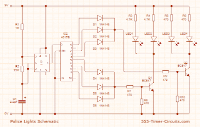
This circuit uses a 555 timer which is setup to both runn in an Astable operating mode. This generates a continuous output via Pin 3 in the form of a square wave. When the timers output changes to a high state this triggers the a cycle on the 4017 4017 decade counter telling it to output the next sequential output high. The outputs of the 4017 are connected to the LEDs turning them on and off.
 |
| Police Lights Circuit Schematic |
Related Posts : 4017,
555,
and,
circuit,
ic,
lights,
police,
with
Subscribe to:
Post Comments (Atom)
hi admin...im using the police light-2 schematic, i want to use 12 red and 12 blue... im a beginner and i need your help...i didnt know how to wire the parts of it...bt if theres a circuit board, maybe understand and know the connections..hope you can provide me the PCB pattern for it and not the schematic... thanx.
ReplyDelete