Wednesday, October 2, 2013
3 channel audio mixer
3 channel audio mixer is built using some of the transistor amplifier.
3 channel audio mixer circuit uses voltage 9VDC summber which can supplied from a battery. 3 channel audio mixer circuit is designed special for the purposes of this Public Amplifier.
Because the audio circuit of this mixer is designed specifically for the purpose of a portable mixer for audio public then this series has only a volume control without the tone control. Image series that looks below audio mixer is a series of mono, if you want to make a 3 channel stereo audio mixer it is necessary to make 2 pieces of a series of three channel audio mixer terebut. For more details, a series of three channel audio mixer can be seen in the following image.
3 channel audio mixer circuit uses voltage 9VDC summber which can supplied from a battery. 3 channel audio mixer circuit is designed special for the purposes of this Public Amplifier.
Because the audio circuit of this mixer is designed specifically for the purpose of a portable mixer for audio public then this series has only a volume control without the tone control. Image series that looks below audio mixer is a series of mono, if you want to make a 3 channel stereo audio mixer it is necessary to make 2 pieces of a series of three channel audio mixer terebut. For more details, a series of three channel audio mixer can be seen in the following image.
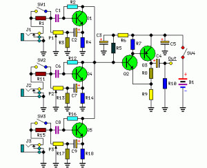 |
| 3 channel audio mixer circuit |
Sign Component Audio Mixer With 3 Chanel Transistor
P1, P2, P3 = 5K
R1, R11, R15 = 180K
R2, R12, R16 = 2M2
R3, R13, R17 = 750R
R4, R14, R18 = 1K
R5 = 15K
R6 = 220R
R7 = 1.5K
R8 = 820R
R9 = 150R
R10 = 100K
C1, C6, C8 = 1μF-63V
C2, C4, C7, C9 = 100μF-25V
C3, C5 = 220μF-25V
Q1, Q4, Q5 = BC550C
Q2 = BC547 should
Q3 = BC557
J1, J2, J3 = 3mm Mono sockets
SW1, 2,3,4 = SPST Toggle
In a series of three channel audio mixer is equipped with a switch on each chanelnya which select the input impedance, when the switch SW1, SW2 and SW3 in the open then the input should come from the output signal with a high level such as VCD, MP3 player, tape, computer and tuner . And at SW1, SW2 and SW3 closed position, the input should come from a weak audio signals such as microphones.

Line Follower Robot Sensor Concept
Line Follower Robot Sensor Concept - Sensor line detector is used in line follower robot is usually based on the principle of light reflectionto distinguish the line with the background color. In the dark color of the light absorption is greater than that of white light reflected to the sensor becomes smaller.
Position sensor to track the trajectory and the example circuit.
 |
| Line Follower Robot Sensor Concept |
Light used for the introduction of the line is usually visible light and infra-red. Sensors for visible light are commonly used are LDR (Light Depending Resistance), while for the infrared light is atransistor and photo diode (photodiode). Sensors placed at the bottom of the frame to hang the robot, so that its position can be located just above the track to be read.
RF Fm 88 108 MHz 20W amplifier
This Fm rf power amplifier has 2 transistors from Philips : BLV 10 and BLW 87. The 2 rf transistors work in class C and this fm amplifier has a total gain of 21dB ( 100 X ) and efficiency 55 – 65%.
One low pass filter with 9 components ensures 60dB rejection on the second harmonic. There is no need for tune-up to cover the whole 88 – 108 MHz FM frequencies.

source [link]
One low pass filter with 9 components ensures 60dB rejection on the second harmonic. There is no need for tune-up to cover the whole 88 – 108 MHz FM frequencies.
source [link]
20W amplifier schematic with mute
This is a series of audio amplifier using ic and equipped with a mute switch. This circuit using ic and has 20W output impedance 4 ohms. Scheme and a list of components can be seen below.

Part List :
Resistor
R1 = 3.3K
R2 = 39R
R3 = 39R
R4 = 3.3K
R5 = 3R
R6 = 3R
Capacitor
C1 = 1uF
C2 = 1uF
C3 = 10uF
C4 = 100uF
C5 = 100uF
C6 = 220uF
C7 = 0.1uF
C8 = 0.1uF
IC
IC = ULN3793W
Tuesday, October 1, 2013
Alarm LED Light Circuit
This circuit yearn for act the performance of the equipment,otherwise Check the fuse here the circuit.The circuit is diminutive and the power supply voltage of all kinds. It demonstrate with LED, 2-color in individual. Which is cathode universal kind,the anode has two separate terminals. If the circuit is functioning well LED, it revealed in wet behind the ears colour.The display is red, as the fuse into the circuit is damaged.The resistor R1 limits the current to gush through the LED is roughly 2 mA.This is an adequate amount to produce the LED light.If it lowers the R1 down, the LED light up.
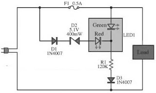 |
| Alarm LED Light Circuit Diagram |
In the conventional setup of the circuit and The fuse is not damaged. The zener diode to prevent the green and red LED illumination up in chorus.Zener diode prevents the LED is simple and red illumination all together.
The piercing efficiency LED, as soon as connected trendy like. The red LED uses high-pressure, so with the intention of single green LED illumination up only. Diodes D3 and D4 wish prevent dodgy instead of the LED. While the semi cycle downbeat voltage of the alternating current voltage.However, if the DC supply voltage.I act not retain to manage diode protection.
6 to 12 Volt Power Supply Inverter
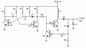
This inverter circuit can provide up to 800mA of 12V power from a 6V supply. For example, you could run 12V car accessories in a 6V (British?) car. The circuit is simple, about 75% efficient and quite useful. By changing just a few components, you can also modify it for different voltages.
Part List:
R1, R4 2.2K 1/4W Resistor
R2, R3 4.7K 1/4W Resistor
R5 1K 1/4W Resistor
R6 1.5K 1/4W Resistor
R7 33K 1/4W Resistor
R8 10K 1/4W Resistor
C1,C2 0.1uF Ceramic Disc Capacitor
C3 470uF 25V Electrolytic Capcitor
D1 1N914 Diode
D2 1N4004 Diode
D3 12V 400mW Zener Diode
Q1, Q2, Q4 BC547 NPN Transistor
Q3 BD679 NPN Transistor
L1 See Notes
MISC Heatsink For Q3, Binding Posts (For Input/Output), Wire, Board
[Continue Reading]
Part List:
R1, R4 2.2K 1/4W Resistor
R2, R3 4.7K 1/4W Resistor
R5 1K 1/4W Resistor
R6 1.5K 1/4W Resistor
R7 33K 1/4W Resistor
R8 10K 1/4W Resistor
C1,C2 0.1uF Ceramic Disc Capacitor
C3 470uF 25V Electrolytic Capcitor
D1 1N914 Diode
D2 1N4004 Diode
D3 12V 400mW Zener Diode
Q1, Q2, Q4 BC547 NPN Transistor
Q3 BD679 NPN Transistor
L1 See Notes
MISC Heatsink For Q3, Binding Posts (For Input/Output), Wire, Board
source:LINK
1000W Power Amplifier
 Power amplifier has up to 1000 Watt power, this circuit made one channel only so if you want to create a stereo in it must be made one again, actually this is more suitable power amplifier in use for Sound System or outdoor, so if only in use for the house I think is less suitable.
Maybe youve seen or even have an active speaker and there is written 1500 watts PMPO (Peak Music Power Output), make no mistake this is different from Power Amplifier Active Speaker, I often dismantle such Active Speaker in it only a power with power no more than 150 watts by using the transformer 2-3 Ampere. PMPO is not a real power which is issued by the Power Amplifier, but counting all the speakers that there is, for example: if there are 5 pieces of speakers on each channel and each speaker has a power of 10 W then it is 100 W PMPO.
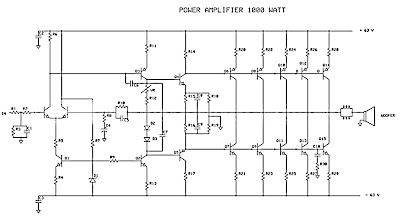 |
| 1000W Power Amplifier schematics |
 |
| Part List 1000W amplifier |
While this 1000 Watt Power Amplifier minimal use transformer 20 Ampere. And the output of Power Amplifier DC voltage contains approximately 63 volts, with currents and voltages of this magnitude, this 1000 Watt Power Amplifier will not hesitate hesitate to destroy your woofer speakers to connect. To overcome that then before the speaker on connects to 1000 Watt Power Amplifier must be in pairs Speaker Protector.
Actually if you want to create a Power Amplifier with great power does not have to make a Power Amplifier with great power. Example: you want to create a Power Amplifier with 10 000 Watt power. You do not have to assemble a Power Amplifier with power of 10,000 watts, but you assemble the power Power Amplifier Small but many, such as you assemble the Power Amplifier with 1000 Watts of power for as many as 10 pieces, it will produce 10 000 Watt Power Amplifier helpless.
Circuit uses power transistors pair of 5 x 5 x 2SA1216 and 2SC2922 and 2SC1583 use a differential amplifier that actually contains 2 pieces of transistors that are in containers together. Why use such built-in amplifier differental tujuanya so identical / similar, could have uses 2 separate transistors but can result in amplifier so it is not symmetrical.
Tips combining speaker.
To get the speakers with great power combining techniques can be used in parallel series, combining each group of speakers should sepaker they will have the same impedance, the same type (Woofer, Mid Range or tweeter) and the same power. Number of merging these speakers should consists of 4 , 9, 16 ff, see picture
 |
| Speaker wiring |
Example: The number of speakers have 4 pieces each of its 200 Watt power generated will be a speaker at = 200 x 4 = 800 Watt. If there are 9 speakers 200 W then the result = 9 x 200 W = 1800 Watt.
Subscribe to:
Posts (Atom)