Showing posts with label polarity. Show all posts
Showing posts with label polarity. Show all posts
Monday, October 14, 2013
Safety Polarity Connection
This electronic project prevents incorrect connection of polarized sources in circuit and is designed using common electronic components. Safety of polarity from the diagram below was dimensioned for a voltage of 12 volts. When connecting correctly voltage to terminals 1 and 2 through RE1 resting contact, diode D1 and the coil current flows once the switch closes the circuit (relay closing, established by contact or connection with device connected).
Safety Polarity Connection Circuit Diagram
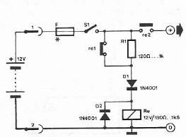
When you connect the wrong polarity of power supply, diode D1 is blocked, the relay no longer closing and power is interrupted device. R1 resistance reduces current flowing through relay coil connected in the state, so that losses to be minimal (the resistance should be chosen according to characteristics of the relay).

Monday, October 7, 2013
Polarity indicator circuit
Is is easy to test the polarity of a circuit’s point whether it is positive or negative by using the tester circuit featured here. The tester circuit has a high input impedance (around 1 megaohms) to avoid loading the point being tested. In testing sensitive points however, (inputs of opamps), the input impedance must be taken into consideration.

The opamp 741 is the core of the polarity indicator circuit. Its non-inverting input is used to test the points for polarity. It has a gain of around 150 which enables it to test low voltage levels. The test result is displayed through the two LED’s D1 and D2. D1 lights up by positive polarity and D2 lights up by negative polarity. Take note that the pin profile on the diagram is based on the TO-5 package profile.
Subscribe to:
Posts (Atom)