Wednesday, November 6, 2013
Mini Roulette Circuit
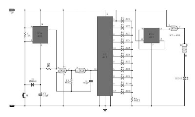
A mini roulette circuit, whilst the switch S1 the output by pin 1 of the IC1a the voltage is “shrill”,The oscillator circuit output IC2b, IC2c go to work.timer pulse generator fed to IC3, a voltage “high” output to the output pins 3, 11, and pin 12 of the IC3, the LED1-LED10 light trail sequence. Section LED11 extravaganza high - low tip. The output of pin 3, 2, 4, 7, 10, of IC3 represented by high points,Output pins 1, 5, 6, 9, 11 in its place of the IC3 with the low points.The bonanza instead of the LED12.The IC1b, IC2a and IC2d in the role of controls.
 |
| Mini Roulette Circuit |
Resistor R2 and capacitor C1 determine the era of the output “shrill” output from pin 1 of the IC1a. The capacitor C1 through R2. at what time you press the switch and the voltage dump across C1 pray regularly raise until the most level. It will reset the flip failure IC1a befall the output by pin 1 is “low”. And the oscillator output circuit to break off working, but in attendance are certain LED light are pending, it can exist with the aim of we put a stop to up being the LED. So fix not apprehension, it choice switch a little time.since, particular a instance full stop with the aim of the R2 and C1. The campaign are compulsory to keep a 6-volt power supply. If tainted is 9 volts, have to try in favor of security reasons.
Related Posts : circuit,
mini,
roulette
Subscribe to:
Post Comments (Atom)
No comments:
Post a Comment
Note: Only a member of this blog may post a comment.