Thursday, October 31, 2013

Ionization Smoke Detector Using A5367

A very simple Ionization Smoke Detector with Interconnect and Timer alarm circuit can be constructed using the A5367 low-current, CMOS circuit that provides all of the required features for an ionization-type smoke detector. A very nice thing at this ionization smoke detector circuit CMOS ic manufactured by Allegro MicroSystems is the interconnection features , which allows as many as 125 units to be interconnected so that if any unit senses smoke all units will sound their alarm. In addition, special features are incorporated to facilitate alignment and test of the finished smoke detector.

This detector needs to be powered by a 9 volts DC power supply (or a 9 volts battery ) .Circuit require few external components and is very easy to be configured . As you can see in this diagram , the sound alarm is “produced “ by an piezoelectric element .

Ionization Smoke Detector Circuit Diagram


Use an external resistor in point A to adjust sensitivity for a particular smoke chamber. Select resistor from point B is to reduce sensitivity during Timer mode.A resistor to VSS or VDD may be added to point C pin to modify low battery voltage threshold. Value of components marked with D will vary, based on the piezoelectric horn used.

An internal timer is provided that can be used in various configurations to allow a period of reduced smoke detector sensitivity, referred to as Timer (or Hush) mode. Internal test circuitry allows low battery check by holding the FEEDBACK and OSC CAP pins low during power-up, then reducing VDD and monitoring the HORN1 pin
[Continue Reading]

Line Following Robot Sensor

This Line Following Robot sensor or surface scanner for robots is a very simple, stamp-sized, short range (5-10mm) Infrared proximity detector wired around a standard reflective opto-sensor CNY70(IC1). In some disciplines, a line following robot or an electronic toy vehicle go along a predrawn black line on a white surface. In such devices, a surface scanner, pointed at the surface is used to align the right track.

IC1 contains an infrared LED and a phototransistor. The LED emit invisible infrared light on the track and the phototransistor works as a receiver. Usually, black colored surface reflects less light than white surface and more current will flow through the phototransistor when it is above a white surface. When a reflection is detected (IR light falls on the phototransistor) a current flows through R2 to ground which generates a voltage drop at the base of T1 to make it conduct. As a result, transistor T2 start conducting and the visual indicator LED(D1) lights up. Capacitor C2 works as a mini buffer.

Line Follower Robot Scanner Circuit diagram:

After construction and installation, the scanner needs to be calibrated. Initially set P1 to its mechanical centre position and place the robot above the white portion of the track. Now slowly turn P1 to get a good response from D1. After this, fine tune P1 to reduce false detection caused by external light sources. Also ensure that the LED remains in off condition when the sensor module is on the blackarea. Repeat the process until the correct calibration is achieved.

The red color LED (D1) is only a visual indicator. You can add a suitable (5V) reed relay in parallel with D1-R4 wiring after suitable alterations to brake/stop/redirect the robot. Similarly, the High to low (H-L) transition at the collector of T2 can be used as a signal to control the logic blocks of the robot. Resistor R1 determines the operating current of the IRLED inside IC1. The sensing ability largely depends on the reflective properties of the markings on the track and the strength of the light output from IC1.
[Continue Reading]

Simple USB player circuit with PCM2902

Usb series player is an electronic device or electronic circuit that functions as an MP3 player that is stored on a storage device such as USB flash.

usb mp3 player


In this usb circuit using an IC as a modifier of digital voice data into analog so that it can be applied to a headphone, or again through the power amlplifier strengthened so that it can be heard through the speakers. IC used in this circuit using IC PCM2902 as a modifier of a digital data into analog data storage.

Below is a schematic diagram of a USB player.
USB mp3 player schematic
Schematic usb player
[Continue Reading]

Simple USB player circuit with PCM2902

Usb series player is an electronic device or electronic circuit that functions as an MP3 player that is stored on a storage device such as USB flash.

usb mp3 player


In this usb circuit using an IC as a modifier of digital voice data into analog so that it can be applied to a headphone, or again through the power amlplifier strengthened so that it can be heard through the speakers. IC used in this circuit using IC PCM2902 as a modifier of a digital data into analog data storage.

Below is a schematic diagram of a USB player.
USB mp3 player schematic
Schematic usb player
[Continue Reading]

Wednesday, October 30, 2013

Digital tone control with MAX5406

The series will I make here is a series regulator of Volume, Bass, and Balance Trable Digital (Tone Control). The core of this circuit is an IC-type output from the Manufacturer Maxim MAX5406, while the IC is an audio processor that comes with the interface switch hit for Tone Control setting above. The circuit scheme is as follows:

The scheme above uses very little supporting components and this makes can be made with a mini size of a matchbox only even if using all SMD components can be reduced in size by half for this time I will only give a simple layout made​​, following picture:

layout components


[Continue Reading]

Simple Source Voltage Protector

Simple Source Voltage Protector
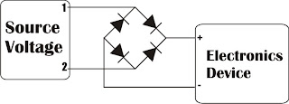
Protection of electronic devices with a DC voltage source of voltage source obligatory reversal, especially protection of the source voltage is reversed. The definition of "Protectors Voltage Sources" in this article are the source voltage surge protector circuit which serves to protect the device from the reversal of the voltage source to the appliance electronics.

Source voltage surge protector will expressed in this article are general, so that later in their applications to stay adjusted value of the component with the voltage source needs an electronic appliance. Let us start reviewing Protectors Voltage Source by simple and modest.

Source voltage protection with 1 diode


Diodes are used as a protector of the source voltage installation tebaliknya voltage source is installed in series with the input line voltage source electronics devices. Installation of surge protector diode as a voltage source is on the positive line voltage source input device. The function is to drain diode current (voltage source) in one direction only, so that in the event of an upside-down voltage source. then the voltage source is not in the channel (in blocks) to the device. The value of the diode is tailored to the needs of the source voltage of the device itself.

Source voltage protection with dioda bridge


Protectors voltage source with a diode bridge in principle the same as the surge protector with a voltage source diode 1 pc. The difference is the source voltage surge protector is not blocking the source voltage, but the source voltage surge protector is to reverse the flow of the source voltage of one polarity in the case of voltage source. From the picture above to explain the purpose of reversing the voltage source in question, namely when given a source voltage through a voltage surge protector is the source of positive polarity (+) will be directly in the stream leading to the positive input line of tools and the source of negative voltage (-) will be directed to the negative voltage source input line tool.
[Continue Reading]

Police Sirine Circuit with IC 555

The series of police sirens with 555 ic this is a series of sirens that utilizes two IC 555 as a pulse generator and producing shrill voice. 

Police Sirine Circuit with IC 555
Both ic 555 respectively build the astable multivibrator circuit and generate output signals with different frequencies. It is intended to be used as one of the high frequency generator or a screeching sound and the other as a regulator of the swing from last shrill voice. If we observe the working principle of this circuit is very similar to a series of modulation fm. Where the shrill sound signal likened to a high frequency signal from the oscillator circuit and control signal swing is the wail of the information signal or input signals that will transmit. This is consistent with the shape of the output signal associated with the loudspeaker, which has an output signal frequency changes in the form of regular meetings wave tenuous.


Actually a series of sirens could be simpler than if you use a 556 IC which is a dual multivibrator or equal to two pieces of IC 555. IC 556 has two multivibrator circuit menfaatkan so you can meet the workflow of this siren sound-producing circuit. Or you can also make it by using a combination of multiple transistors. And it could be you do remember the oscillator circuit can be easily made with transistors.

Appropriate image above then:
R1, R2, and C1 is a determinant of the frequency of the signal generated by IC1
R3, R4 and C3 is a determinant of the signal frequency whine
Signals generated by IC1 IC2 pin 5 connected to the control signals intended for the resulting shrieks
Screeching sound signal will swing to follow the control of the output signal IC1
You can do experiments in order to gain more understanding of police sirens this circuit by changing the value of some critical components such as the frequency of R1, R2, R3, R4, C1 and C3.
[Continue Reading]

Tuesday, October 29, 2013

High End Power Amplifier Wiring Circuit


As the causes of the heat sink mounting surface to approximately 6 mm from the edge of the circle are fixed, assuming that the amplifier circuits mounted directly on the rails. This means that the leads of the transistors must be folded twice, so they are positioned properly, without a permanent mechanical stress in transistors. For high output transistors, the first corner a little closer to the plastic packaging than expected (in the wide part), otherwise the son of the rails or not to strike. Another possibility, which has the disadvantage that it weakens the structure, it is to grind enough metal in appropriate locations, to provide sufficient clearance. We have consciously rejected that option.

High-End Power Amplifier Wiring Diagram

Once you have taken on these details and transistors can be easily placed on the free flat heatsink with her son through the holes in the circuit you can use the locations of the holes on the back mark of the radiators. Of course you must do so before the transistors are soldered to the track but is according to the holes for the final determination of the amplification circuits made in the base plate. Once the output transistors and their driver were mounted on the heat sink and soldered to the boards, the bottom plate can be removed easily.

Be careful not too much force on the terminals of the transistors, if the plates are exposed in this way.
Power transistors T14 and T15 must be mounted on heatsink bs with insulators (mica discs), while the other three transistors (Til, T12 and T13) can be screwed directly onto the heat sink. Make sure you use thermal paste to all the transistors.

After all the holes for the remaining circuits, transformers, switches and lights (front) and the ventilation slots in the chassis, you can screw up everything and you install the wiring.

Use well-designed audio cable connected to the input of the amplifier boards on the terminals in the vicinity of the inputs on the board overdrive display. With the two ground terminals to the input jacks for connecting the housing to the grounds of the two channels. This will avoid creating loops. The inputs to the outputs of the amplifier are in the middle of the board control overdrive removed. The best way to connect, to use thin, flexible cable, to connect the output jacks.
[Continue Reading]

20 Watt Schematics power amplifier

This circuit is mono amplifier use IC TDA1010A .Minimum voltage require 4V and maximum voltage 24V. To avoid damaged IC please use supply voltage 12 volt and must be filtering voltage. Power output 20 W with impedance 4 Ohm. IC equation with : TDA1011, TDA1011A , TDA1015 , and TDA1020.
See circuit schematic and troubleshooting amplifier :

If circuit circuit above not working , errors may occur in :
  • Supply Voltage.
  • Damaged Component , such as : IC , resistor or capcitor.
  • Input output cable not connected.
  • Damaged speaker.
  • Short-circuit input with ground.
Can be used for :
  • Tuner
  • Pream Head / Tape
  • Mic
  • CD or DVD player
  • PC
  • MP4 player
  • etc.
[Continue Reading]

2 X 0 32W BA5386 amplifier schematic

Amplifier circuit above scheme is a combination of the two IC was then made into one of its supply voltage so it does not require a lot of supply voltage and output a stereo input. Output issued also very low at 2 X 0.32 W and has 8 ohm impedance. Indeed, this amplifier has a very low output, but the amplifier is quite easy to make and does not require much cost. The voltage required at least 4 volts while the maximum supply voltage of 12 volts.
BA5386 amplifier
Part List :
R1,R2______50K trim
C1,C2______3u3F
C3,C4______100uF
C5,C6______470uF
U1,U2______BA5386
[Continue Reading]

FPF270X Over Current Protection

Using the FPF270X adjustable over-current protection IC can be designed a very simple adjustable current-limiting electronic project .FPF270X provide full protection to systems and loads from excess current conditions.Minimum current limit is adjustable from 0.4A to 2.0A.The input voltage range is 2.8V to 36V. Loads can be activated or deactivated with a low-voltage logic compatible ON pin. Fault conditions can be monitored using the error flag pin and/or the power-good pin.


Over current protection using FPF270X

All devices clamp the load current so that it cannot exceed an externally programmed current level. An over temperature feature provides further device protection in case of excessive levels of power dissipation.
FPF2700 responds to an overload condition that lasts longer than a fixed blanking period by turning off the load, followed by a retry after the auto-restart time.The FPF270X has an adjustable 0.4A to 2.0A minimum current limit set through an external resistor, RSET, connected between ISET and GND.A 4.7 F to 100 F ceramic capacitor is adequate for CIN in most cases. Larger CIN values may be required in high-voltage or high-current applications.

Over current protection using FPF270X

A 0.1 F to 1 F capacitor, COUT, should be placed between the OUT and GND pins. This capacitor helps prevent parasitic board inductances from forcing the output voltage below ground when the switch turns off.
During a hard short condition on the output while operating at greater than 24V VIN, a large instantaneous inrush current is delivered to the shorted output. A capacitor must be placed at the OUTPUT pin, acting as a current source to support the instantaneous current draw (Table 2).

Over current protection using FPF270X

For more details about how to design a protection circuit using FPF270X IC please consult the manufacturer datasheet.
[Continue Reading]

Monday, October 28, 2013

Essential Home Theater Design

Relations every time require to bring habitat particular luxurious home entertainment structure. This is for the reason that just very a small number of households can afford home drama system. Of tardy, only the rich and the famous can afford such luxury. This notion is right away a feature of the ancient history. Home plays systems may well now stay vacant to greater numeral of households since of the familiarity of principal home drama design. The basic home theater design may well just require three basic components and these three components might already take place within your means in lieu of the working course group.

However, formerly you could need to think of the vital home-made show business design for your home theater organism, you may perhaps need to know the size of the scope for the home the stage stubborn up. The size of the scope to someplace the home drama want transpire set up will depend on how straightforward the home show business design needs to be.

Home theater experts recommends with the purpose of if the scope is quite diminutive, all you need pro your home plays design is a television set, three speakers and a DVD player. The home show business design may perhaps be there dependent of the shpre of the opportunity; however, the put of the speakers remains to be the not here, the aptly and the meeting place of the space. central residence show business design may perhaps require a television set superior than 27 inches. Too diminutive screen in support of your home drama design can not exist sufficient for a picture acting-like experience.

This is for the reason that even for the home acting design, you might need to consider the sight and sound of a picture drama. It is the chief consideration why dwell in stab to a show drama, the immense screen and the surround sound. With respect to the surround sound of a picture plays, the major three speakers is barely applicable on behalf of lesser quarters, if the space is larger, the local the stage design needs to take place added than three, you may perhaps go up to six speakers and a complimenting subwoofer may be needed for the surround effect. leaving back to a trivial space, if you force lone locate three speakers, you may perhaps care for to consider export a tall quality brand loudspeaker; this will make happen you adequate surround sound on behalf of a less significant scope.

If you boast a slight finances, ensure with the aim of the stockpile someplace you preference believe your speakers will allow you to test the outcome modish your opportunity and if it will not give you a fine surround sound, they be supposed to allow you to return before return the constituent. This is as roughly speakers sound good in the store but what time you at the end of the day suite them up in a insignificant opportunity, the effect is not very good. observe a neat deal wherever they can allow you to return otherwise restore the speakers. However, if your resources is sufficient, you might consider hiring the services of a residential home the stage designer. Your home theater designer wish be alive able to design the home acting better and with complete accessories. He may possibly require read-through the power rating, and the need in support of amplifiers. He may well too put in a good word for using home plays projectors and he may recommend how the speakers need to befall. You yearn for dig up a profit home drama design if you will be able to hire home drama designers. The need in favor of home theater seats and television cabinet may possibly additionally be vital for the complete package of your home acting.

You may possibly take pleasure in the entertainment exclusive of having to tide traffic jam and enjoy hip your own place of origin show business scheme.
[Continue Reading]

Guitar Control Circuit Diagram

Guitar Control Circuit DiagramGuitar Control Circuit Diagram

Device purpose:

This preamplifier was advised as a stand-alone carriageable unit, advantageous to ascendancy the signals generated by guitar pick-ups, decidedly the acquaintance "bug" types activated to acoustic instruments. Obviously it can be acclimated with any blazon of apparatus and pick-up.

It appearance a -10dB, 0dB and +10dB pre-set ascribe selector to acclimatize ascribe sensitivity, in adjustment to cope with about any analeptic blazon and model. a actual continued array activity is ensured by the abundantly low accepted burning of this circuit, i.e. beneath than 800µA.

Circuit operation:

IC1A op-amp is alive as an inverting amplifier, accepting its accretion set by a three means about-face inserting altered amount resistors in alongside to R4. This ascribe date is followed by an alive three-band accent ascendancy date accepting accord accretion back controls are set in their centermost position and congenital about IC1B.

[Continue Reading]

Melody Generator using M66T

Melody Generator using M66TMelody Generator using M66T


This is the actual simple way to comedy a song with distinct 1.5 battery. You can body this circuit for allowance acceccories. When the allowance opened, again a song will be played.. It’s accessible and bargain right..? :D . It aloof use a distinct baby dent which will accomplish a song which already buried central the chip.


Components List:

C = 1uF

R = 4.7KW

Q = 2SC9013

About IC M66T series:

The M66T series is a CMOS LSI designed melody generator IC for use in telephones and toys application. It has an on-chip ROM programmed for musical performance. Produced by CMOS technology, the device results in very low power consumption. And with built-in RC oscillator, a compact melody module can be constructed with only a few additional components.

M66T pin assignment:


  • Pin 1 (O/P) Melody Output
  • Pin 2 (Vdd) Positive Power Supply
  • Pin 3 (Vss) Negative Power Supply

The following are the M66T series and the song generated by its series:

  • M66T-01L : Jingle Bells + Santa Claus Is Coming To Town + We Wish You A Merry Christmas
  • M66T-05L : Home Sweet Home
  • M66T-09L : Wedding March (Mendelssohn)
  • M66T-19L : For Alice
  • M66T-68L : It Is A Small World
[Continue Reading]

Sunday, October 27, 2013

Direction Sensor CMPS03

Direction Sensor - CMPS03
CMPS03 Compass Module Overview
Compass is a tool for navigation for a direction, a direction in this article referred to is the magnetic module CMPS03 Compas. Magnetic Compass Module CMPS03 often used in making robots in the contest.

Magnetic Compass Module Functions in the contest  CMPS03 usually to provide a reference where the robots are in position and lead anywhere, then the position and direction provided by the Magnetic Compass Module reference sebgai CMPS03 the next robot motion. Magnetic Compass Module uses I2C data communication lines to mirokontroler. With adalanya I2C data communication lines from this CMPS03 this module can be connected directly to a microcontroller that suport with I2C data communication channels such as AVR ATMega. Magnetic Compass Module CMPS03 require 5 V voltage with 15mA current.

Direction Sensor - CMPS03
CMPS03 Circuit Diagram


Because the module using I2C Magnetic Compass CMPS03 we can use 5 lines are:
VCC + 5 V on pin 1
SCL with Pull Up resistor 10 K
SDA with Pull Up resistor 10 K
Calibrate the PIN associated with micro switch 6
Ground on PIN9
[Continue Reading]

Subwoofer Filter and Low Pass Filter with LM741

The acoustics of converting a filter, there are many aspects of the economic viability of the more famous are baxandal filter low and high frequency filters and crossover Acoustic space is transformed into sub-domains, so that the Thursday Speakers. Applications, we offer a filter, the limits of the region to transform acoustic (20-20000Hz) in the region of 20-100Hz.

Subwoofer Filter and Low Pass Filter Circuit Diagram


The signal for a first high pass filter C1, C2, P1, which is undesirable level DC input. A lowpass filter consisting of R3, R4, C3 prevents frequencies above 10 kHz, which do not benefit from this design, and it would be that the instability and noise. The summary amp invert signal.

The low Summary of the amplifier signals go to a second low-pass filter to prevent the frequency from the speakers. I decided, a second order, as this box with a closed place feature. If you have a circuit with a valve system, and then simply close the Wind (Roll a pair of socks and pick at the port / Wind), this will give you a sealed box instead.
[Continue Reading]

0 15Watt amplifier schematic

TA7066 amplifier circuit
Amplifier circuit is also very suitable when used in fm radio receiver. Supply voltage required 8 - 25 Volt DC with a maximum output power 0.15W.See Schematic below.
Part List
R1 = 100R
C1 = 1nF
C2 = 4.7uF
C3 = 10uF
C4 = 100uF
C5 = 47uF
C6 = 4.7nF
U1 = TA7066
[Continue Reading]

32 768 KHz Oscillator using Watch Crystal

32.768 KHz Oscillator using Watch Crystal32.768 KHz Oscillator using Watch Crystal

a 32.768 KHz square wave from a common watch crystal. The output can be fed to a 15 stage binary counter to obtain a 1 second square wave. The circuit on the left using the 4069 inverter is recommended over the transistor circuit and produces a better waveform. The single transistor circuit produces more of a ramping waveform but the output swings the full supply voltage range so it will easily drive the input to a CMOS binary counter.
[Continue Reading]

Saturday, October 26, 2013

RS232 to RS485 Circuit

The new archetypal of RS485 advocate overcomes the RTS controlled botheration accomplished by our chargeless design. However, to do that requires a microprocessor, so there is a greater complication to the design. We advertise this unit, although currently we are attached our sales to barter who can pay by coffer alteration – which in absoluteness is bounded Australian companies. 

This architecture has been almost agitation free, and if you crave quantities we can acclimate the adapter pinout to clothing your appliance – about again the accessory will no best fit the simple little D25 case in which you see it pictured.

Click image to view larger RS232 to RS485 Circuit

* Data (vs RTS) controlled – does not rely on PC handshake timing
* DB25 RS232 connector compatible with PC
* TxD and RxD translated from RS232 to RS485
* Direction of transmission controlled by Data
* Handshake loop the PC connection so it works with all software
* RS485 signals output on D9 male with lots of Ground pins
* Indicator LED(s) to show communications traffic
* Line powered – powered by RS232 handshake lines
* RS485 Termination resistor not included
* Pullup/Pulldown resistors on RS485 to establish line-idle condition
* Baud rate is dipswitch selectable 1200 – 115.2k
[Continue Reading]

3 Band Tone Control with LF351

3 Band Tone Control circuit uses an op-amp as an amplifier end. Tone Control circuit is a regulator of tone bass, midrange and treble or 3 band called because it can set the three tones. Filter circuit is applied to the series of "Tone Control 3 band" This type baxandal like the title of this article. 

Results filtering regulator tone or tone control baxandal type is good, because there is no signal level is wasted directly into the ground. Range frequency tones generated from Tone Control 3 band was determined by the configuration of the R and C of the filter section baxandal. As an amplifier on Tone Control The set of three band use traditional IC LF351 has slewrate high and high input impedance. For more details, series 3 Band Tone Control as follows.

Figure Series 3 Band Tone Control

3 band tone control

3 Band Tone Control circuit above using LF351 Op-Amp is used to strengthen the signal after filtering by the filter process baxandal. Level tone Bass, Midrange and Treble settings are determined by potensio R1, R2 and R3. Frequency filter in the circuit above baxandal to 50 Hz bass tone, tone Midrange 1 KHz and 10 KHz for Treble tone.
[Continue Reading]

Crystal Radio Audio Amplifier Circuit

Crystal Radio Audio Amplifier CircuitCrystal Radio Audio Amplifier Circuit


Here is a simple audio amplifier application a TL431 blow regulator. The amplifier will accommodate room-filling aggregate from an accustomed clear radio outfitted with a long-wire antenna and acceptable ground. The chip is agnate in complication to a simple one-transistor radio but the achievement is far superior.


The TL431 is accessible in a TO-92 amalgamation and it looks like an accustomed transistor so your hobbyist accompany will be afflicted by the aggregate you are accepting with alone one transistor! The amplifier may be acclimated for added projects, too. Higher impedance headphones and speakers may additionally be used. An earphone from an old blast will accord boisterous aggregate and abundant sensitivity! The 68 ohm resistor may be added to several hundred ohms back application aerial impedance earphones to save array power.
[Continue Reading]

Stepper Motor Controller Using by A3952S

Using the A3952S stepper motor controller ( designed by Allegro MicroSystems ) we can design a very simple and useful motor driver circuit that can be used in many electronic applications . A3952S stepper motor controller is capable of continuous output currents up to 2 A and operating voltages range up to 50 V. Internal fixed off-time PWM current-control circuitry can be used to regulate the maximum load current to a desired value. The MODE terminal can be used to optimize the performance of the device in microstepping / sinusoidal stepper motor drive applications.

A3952S Stepper Motor Controller Circuit diagram


When the average load current is increasing, slow-decay mode is used to limit the switching losses in the device and iron losses in the motor. The thermal performance in applications with high load currents and/or high duty cycles can be improved by adding external diodes in parallel with the internal diodes. In internal PWM slow-decay applications, only the two top-side (flyback) diodes need be added. For internal fast-decay PWM, or external PHASE or ENABLE input PWM applications, all four external diodes should be added for maximum junction temperature reduction .

As you can see in the schematic diagram , this stepper motor driver circuit require two A3952S circuits and other few additional electronic components.
[Continue Reading]

Friday, October 25, 2013

Self Installation of Auto Sound System can Save Serious Cash

If you are seriously hoping to save a significant chunk of change when it comes to your auto sound system, you should consider saving on installation. Under ordinary circumstances I urge people to be very, if not overly cautious when it comes to installing your own auto sound systems. The thing is, that some people really are talented when it comes to activities such as this. Beyond talent, some people have frightening skills with electronics and if you are one of those, then by all means consider the money you could save yourself (or the extra money youd have to invest in your system?).


We all know that money doesnt grow on trees and when youve been saving up for quite a while to get the sound system you really want its a serious joy killer to have to wait another month or two in order to save up enough money to cover the cost of the installation of your sound system. If you or someone you know and trust (trust being the operative word in this instance) can do the work, it makes no sense from a fiscal point of view to pay someone else to do it.

That being said, if there are any doubts about your skill or experience you might want to at the very least get a second opinion or price installations in your area to see if it might actually be worth saving a little more. Time is another important issue when it comes to the installation of an auto sound system. It doesnt matter how capable you are of making the installation if you simply lack the time to do it. In cases such as this it would have been just as wise to go ahead and pay someone to make the installation. It makes much more sense to me than having the system sitting in a box for months on end while you wait for the time to get it taken care of.

I am one of those people who firmly believes that time is money. Time lost from work is expensive. This is especially true when the times of 10 or more people are lost. It adds up quickly no matter if you have a small or a large company. Time is also (unfortunately) the one commodity in life that you can never recover. No matter how hard you try you cannot recapture time that has been lost. If you have children you know exactly what Im talking about (particularly if your children are either teens or grown and gone). You cannot recover lost time so make sure you arent wasting your time by trying to install an auto sound system that is beyond your abilities.

Dont fret though. Most of us find that at some point in our lives we are limited by either time or money if not both. If everything was quick and easy we wouldnt really have anything worth working for would we? Consider all your limitations when planning and purchasing your auto sound system and make sure that the system you select falls squarely within your ability to install, your time limit for installation, or your price range for affording to pay for the installation. Whether you decide to do your own installation or have a professional installation of your auto sound system the prize is the superior sound quality you will be able to enjoy.

[Continue Reading]

Emergency Light Flashlight

3 in 1 - LED Night Light, LED Emergency Light and LED Flashlight; Length: 4.0". The Night Light has an Automatic Sensor which allows On at Dusk and Off at Dawn. The Emergency Light features an 8 Hour Battery Back Up. Convenient White Light Flashlight.

The light is not terribly sharp-witted but its first-class sufficient to facilitate you wont be real bumping into furniture all through a power outage. The light is by the side of its brightest at what time the power is rotten.
When its used having the status of a nightlight it is a not much dimmer but still upbeat adequate to perceive your way around.

Emergency Light, & Flashlight
The intensity of the light motivation vary depending on how dark the opportunity is. during the belatedly afternoon while the sun is still outside it will live very dim but will perk up up being the extent becomes darker. Although here is a photo sensor on the light a loss of power preference aim the light on in spite of of how dark before light the area is.

The light stays on a bunch longer than the circular emergency plug concerning illumination with the aim of Ive used in the older and it looks a lot better than them. I carry out think it would look even better devoid of the flashlight part of the light and I would have a preference to grasp a version like with the aim of if theyd offer it.

Once plugging into a lookalike outlet it still leaves area intended for a lesser plug to progress into the outlet then to it.
[Continue Reading]

Simple But Reliable Car Battery Tester

This circuit uses the popular and easy to find LM3914 IC. This IC is very simple to drive, needs no voltage regulators (it has a built in voltage regulator) and can be powered from almost every source. This circuit is very easy to explain: When the test button is pressed, the Car battery voltage is feed into a high impedance voltage divider. His purpose is to divide 12V to 1,25V (or lower values to lower values).

This solution is better than letting the internal voltage regulator set the 12V sample voltage to be feed into the internal voltage divider simply because it cannot regulate 12V when the voltage drops lower (linear regulators only step down). Simply wiring with no adjust, the regulator provides stable 1,25V which is fed into the precision internal resistor cascade to generate sample voltages for the internal comparators. Anyway the default setting let you to measure voltages between 8 and 12V but you can measure even from 0V to 12V setting the offset trimmer to 0 (but i think that under 9 volt your car would not start).

 Car Battery Tester  Circuit diagram:


There is a smoothing capacitor (4700uF 16V) it is used to adsorb EMF noise produced from the ignition coil if you are measuring the battery during the engine working. Diesel engines would not need it, but Im not sure. If you like more a point graph rather than a bar graph simply disconnect pin 9 on the IC (MODE) from power. The calculations are simple (default)
For the first comparator the voltage is : 0,833 V corresponding to 8 V
* * * * * voltage is : 0,875 V corresponding to 8,4 V
for the last comparator the voltage is : 1,25 V corresponding to 12 V
Have fun, learn and dont let you car battery discharge... ;-)

author: Jonathan Filippi
e-mail: jonathan.filippi@virgilio.it
[Continue Reading]

Thursday, October 24, 2013

Alpine Audio Amplifier 500 Watt RMS

Alpine Audio Amplifier 500 Watt RMS
Alpines Amplifier to chain is a good series of normal-grade amplifiers. They arent lofty terminate, but they value is isnt "high end" either. They are efficient and control well with vehicles with the purpose of dont exactly say a bundle of further amps free in support of powering amplifiers. I run an MRP-M500 and an MRP-F300 arrived my Honda Fit and they both supply me with capable, clean power not including taxing my cars electrical usage.

In my system, the M500 is powering a 12" subwoofer in a insignificant, sealed box. with the purpose ofs not exactly a formula meant for greatest extent deep shock, but the M500 does a major occupation pushing my subwoofer to its fullest budding. The classify-D circuitry makes the amp very efficient so with the purpose of it bidding effort well clothed in nearly all vehicles electrical systems.

The lone downside Ive found is to the EQ functions are relatively inadequate. You comprehend controls designed for hub frequency, crossover advantage, and low boost. It makes it a minute other intricate to get a smooth sound flanked by this amp and your four-channel amp. It presently takes longer than if in attendance were supplementary EQ controls. too, the low boost puts a definite crest voguish its frequency output so so as to the amplitude drops sour higher than and underneath the inside frequency. That earnings that if you like to step the greatest power output, your range is open to come to pass somewhat inadequate.

Overall, Im very glad with the M500. seeing that extended as youon the subject of not looking to power a massive, inefficient subwoofer, it be supposed to donate you a very smooth, musical sound.

MRP-M500 - Alpine Monoblock 500 Watt RMS Power Amplifier  :

Product Features

  • Mono subwoofer car amplifier
  • 300 watts RMS x 1 at 4 ohms (500 watts RMS x 1 at 2 ohms)
  • Class D amp with MOSFET power supply
  • 10-11/16"W x 2-7/16"H x 9-9/16"D

Technical Details

  • Brand Name: Alpine
  • Model: MRP-M500
  • Faceplate Type: Detachable
  • Device Type: Amplifier
  • MP3 player: N
  • Warranty: 1 year warranty

[Continue Reading]

Isobaric loading Subwoofer Box

Isobaric is not in reality an inclusion type but a woofer loading method. Isobaric loading can be there used fashionable conjunction with several of the area types, not including perhaps never-ending baffle. Isobaric loading consists of two woofers coupled at once by a suddenly field which is simply slow a sufficient amount to prevent the two woofers from striking solitary an added. The woofers possibly will take place mounted look to face, back to back otherwise front to back. However it is essential to exhibit the woofers firing within time with lone any more.

Isobaric loading Subwoofer Box

In order to accomplish this with the woofers firing front to front or else back to back individual of the woofers orator leads be obliged to be real reversed with respect to the other woofer. Isobaric loading is regularly used whilst place is on a premium before a top figure amount of woofers desire to be used featuring in a particular volume of space. By isobarically loading the woofers, a box of barely partly the size of a individual woofer box is desirable. pro pattern, if a 12″ woofer requires a two cubic end box, the same 12″ woofer isobarically loaded lone requires a lone cubic bottom box. The cost of this design, other than doubling the woofer cost, is a reduction featuring in the subwoofer usage efficiency by three decibels (if both woofers are prearranged the same power at the same time as a single woofer), which is equivalent to halving the amplifier power. extra, minor box subwoofer designs enclose all but eliminated the need in support of isobaric loading in car audio and it has fallen vetoed of popularity.

Advantages of this design are increased linearity voguish the orator movement, let fall legroom supplies, and increased power conduct. Disadvantages are increased cost, increased design and compilation complexity, and decreased efficiency.

[Continue Reading]

Wednesday, October 23, 2013

LM2901 LED bar graph meter

Several LED above and other components used to determine the signal amplifier, when in a state of high and low . If the signal received from the amplifier circuit is high then the LED lamp are lit up everything and more bright LED lamps, but otherwise if the received signal is low then the lights on only one or two , even absent or faint.

To use the circuit you can connec with the output amplifier or speaker output , if there is reinforcing the other in the amplifier , can be connected to the output.
Led signal meter
[Continue Reading]

Mini Subwoofer 5 6 Bandpass 4th Order Isobaric
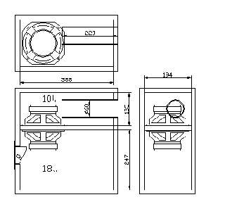
The order of 4 or sealed rear chamber bandpass system is essentially a system of watertight enclosures with the addition of an acoustic filter for the driver. The resulting system usually provides a lower cut-off frequency, the compromise that a larger case. The space can be reduced by two drivers in isobaric configuration.

4th-order bandpass systems generally show better able to handle the functions that the other major systems are considered. The transient response and is second only to the sealed enclosure systems, making it a good choice for subwoofer applications.

Since all output 4th order bandpass system is via the port, the largest diameter possible for the port area should be used to minimize noise from the port. The ports must be incinerated where possible, for the same reasons.

Mini Subwoofer 5 -6" Bandpass 4th Order Isobaric
4th order Isobaric Subwoofer Box Design

The 4th order bandpass system rarely allows a perfect bandpass response - there is usually an out-of-band noise present in the production. A notch filter can be used simply to reduce the noise as audible. Otherwise, a lowpass filter used in series with the driver, but the in-band response system may be affected if this approach is taken.

As the speaker sound 4th order band pass issued by the openings or ports on the port side of the box, the port noise inevitable.

This unwanted noise can be minimized by a notch filter and the largest diameter possible for the port of the area should definitely be used. Another option is to burn the ports of the 4th order bandpass room as this will certainly help to reduce unwanted extra from the subwoofer.

WOOFER / MID MODEL - 5MP60 / N
Specifications :
  • Nominal Basket Diameter 5 "/ 125mm
  • Impedance 8 ohm
  • RMS Power 50 Watts
  • Program Power 100 Watts
  • Frequency response 50Hz - 12.0kHz
  • Sensitivity (1W/1m) 91dB
  • Voice Coil Diameter 1 "/ 25.8mm
  • BL Factor 6.4 N / A
  • Voice Coil Length 14 mm
  • Air Gap Height 6mm
  • X Damage (peak to peak) 20 mm
  • Magnetic Assembly Weight 2.2 lbs / 1.0 kg.
  • Edit Information
  • Diameter 5.28 "/ 134mm x 5.28" / 134mm
  • Bolt Circle Diameter 5.4 "/ 137mm
  • Baffle Cutout Diameter --
  • - Front Mount 4.72 "/ 120mm
  • Many of the 4 mounting holes
  • Volume displaced by driver, 019 m 3 / .5 liter
  • Total Depth 2.68 "/ 68mm
  • Net weight 2.64 lbs / 1.2 kg.
  • Weight 2.8 lbs / 1.27 kg.
  • Materials
  • Basketball aluminum diecast
  • Polypropylene cone
  • Rubber Surround
  • Voice Coil Wire Copper
  • Ferrite
  • Thiele-Small Parameters
  • Resonance Frequency (FS) 60 Hz
  • Impedance (Re) 5.33 ohms
  • Coil Inductance (Le) 0.4 mH
  • Mechanical Q (Qms) 1.604
  • Electrical Factor (Qes) .35
  • Total Q (Qts) .29
  • Comp. Equivalent Vol. (Vas) 35 FT3 / 9.8 Liter
  • Voice Coil Overhang (Xmax) 4.0mm
  • Reference yield 5%
  • Volume Displacement 34 cm3

Source : alectronics.blogspot.com
[Continue Reading]

Class A headphone amplifier

Class A headphone amplifier
[Continue Reading]

Tuesday, October 22, 2013

Auto Alarm Schematic

In operation, the alarm circuit allows a 0 - 47 second time delay, as determined by the R1 /C1 combination, after the switch is armed to allow the vehicles motion sensor to settle down. This allows you time to get a bag of groceries out of the trunk and not have the hassle of juggling the groceries and the key switch at once.

During the time delay, half of LED1, which is actually a single, bi-colored, three-legged common cathode device, lights green. At the same time, pins 8 and 4 of U2 (a 555 oscillator/timer) are held low by Ul (a 3905 oscillator/timer), causing the alarm to remain silent. Once the delay is over, LED1 turns red, indicating that the circuit is armed.

Auto Alarm Schematic Circuit Diagram


At that point, a ground at pin 2 of U2 forces pin 3 of U2 high, closing the contacts of Kl and sounding the siren for a time duration determined by R4 and C2. Once the time has elapsed, pin 3 is pulled low, Kl opens, and the circuit is again ready to go. The circuit can be manually reset by the simple expedient of opening and closing the key switch. Potentiometer R3 controls the LEDs illumination intensity.

Diode D1 ensures that the green segment of LED1 is fully extinguished when Ql is turned on-which turns the LED to red. Resistors R4 and R5 must be connected to the + V bus. not to pin 7 of Ul. otherwise U2 will mysteriously trigger itself each time the initial delay ends.
[Continue Reading]

Preamplifier Circuit Diagram DCF77

DCF77 Preamplifier Circuit Diagram A popular project among microcontroller aficionados is to build a radio-controlled clock. Tiny receiver boards are available, with a pre-adjusted ferrite antenna, that receive and demodulate the DCF77 time signal broadcast from Mainf lingen in Germany.
DCF77 has a range of about 1,000 miles. All the microcontroller need do is decode the signal and output the results on a display. The reception quality achieved by these ready-made boards tends to be proportional to their price. In areas of marginal reception a higher quality receiver is needed, and a small selective preamplifier stage will usually improve the situation further. 

The original ferrite antenna is desoldered from the receiver module and connected to the input of the preamplifier. This input consists of a source follower (T1) which has very little damping effect on the resonant circuit. A bipolar transistor (T2) provides a gain of around 5 dB. The output signal is coupled to the antenna input of the DCF77 module via a transformer

Circuit diagram: 
Preamplifier Circuit Diagram
DCF77 Preamplifier Circuit Diagram

DCF77 Preamplifier Circuit Diagram The secondary of the transformer, in conjunction with capacitors C4 and C5, forms a resonant circuit which must be adjusted so that it is centered on the carrier frequency. An oscilloscope is needed for this adjustment, and a signal generator, set to generate a 77.5 kHz sine wave, is also very useful. This signal is fed, at an amplitude of a few milli-volts, into the antenna input. With the oscilloscope connected across C4 and C5 to monitor the signal on the output resonant circuit, trimmer C5 is adjusted until maximum amplitude is observed.

It is essential that the transformer used is suitable for constructing a resonant circuit at the carrier frequency. Our proto-type used a FT50-77 core from Amidon on which we made two 57-turn windings. It is also possible to trim the resonant frequency of the circuit by using a transformer whose core can be adjusted in and out. In this case, of course, the trimmer capacitor can be dispensed with. Rainer Reusch Elektor Electronics 2008
[Continue Reading]

The pair of transistors power amplifier

Already Know about the transistor above? transistor above is one of the transistors that are applied at the amplifier end audio amplifiers. Because the power output and good quality of this transistor is very popular with high-power amplifier makers.
Transistors on no other than is 2SC2922 and 2SA1216, transistor pair is already very well known as a reliable amplifier. With a price not too expensive and not too large transistor large is also very suitable. And this transistor has its own code for its quality, its code is like 5DY, 57P, 85Y, 92P, etc.. to see datsheet transistor can be seen below.

Maximum Voltage  180V
maximum collector current  17A
Total power output  200W
To more clearly and accurately datasheet can be found here.
[Continue Reading]

Vertical IC Configuration

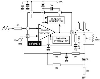
Various kinds of vertical out IC configuration. Ac coupling -connect from the yoke deflection output to a coil connected directly. Dc coupling - connected the output to the coil through a capacitor deflectioan yoke. Electrolityc Capacitors (usually worth 1000u/35v). This configuration requires two kinds of voltage (the voltage mirror plus-minus). Dc input coupling using diffferential - uses 2 input from the driver IC.

Vertical IC Configuration AC Coupling

Vertical IC Configuration DC Coupling

[Continue Reading]

Monday, October 21, 2013

High voltage inverter circuit diagram

high voltage inverter circuit
This inverter circuit works with a transistor and transformer and other components to increase the voltage becomes high. Input supply voltage ranging from 3V to 6V DC, later it was raised to high voltage AC. However, in this inverter circuit output current is very small, probably under 0.1A even smaller. However, its use you can apply it on a fluorescent lamp 10W maximum power only, and that too takes time to switch on fluorescent lamps.
Part List
R1 = 4K7
R2 = 2K2
R3 = 330K
C1 = 100nF
C2 = 100nF 275V
C3 = 0.22uF 275V
Q1 = D506
L1 = 100 times winding, with 0.8mm diameter copper wire
L2 = 50 times winding, with 0.8mm diameter copper wire
L3 = 5000 times winding, with 0.4mm diameter copper wire
[Continue Reading]

Audio amplifier with IC AN7522 AN7523 and TDA2616

Audio amplifier with  IC AN7522, AN7523 and TDA2616
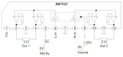
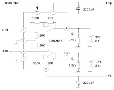
The series of amplifiers that are used on the television audio, amplifier used amplifier ICs, including the IC:
• AN7523
• AN7522
• TDA2616


Third series of the function with the same system, namely BTL (Bridge Transformer Less). By using such configuration we get several advantages, namely no use coupling capacitors or coupling transformers.


Block diagram of circuit in the IC AN7522, AN7523 and TDA2616 as in the image below :

Schematic AN7522
Schematic AN7522
AN7523 amplifier schematic

AN7523 amplifier schematic
Schematic TDA2616


[Continue Reading]